• Modelers Alliance has updated the forum software on our website. We have migrated all post, content and user accounts but we could not migrate the passwords.
    This requires that you manually reset your password.
    Please click here, http://modelersalliance.org/forums/login to go to logon page and use the "Forgot your Password" option.

Military Bulldozer X3

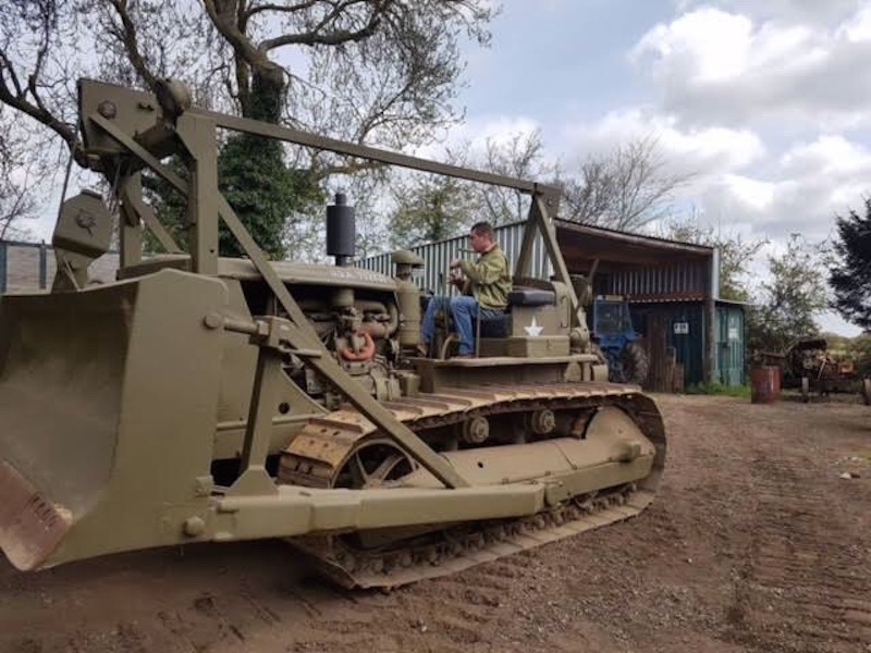
Bob, one thing to keep in mind is that as the track rails wear and the pins and bushings get loose, the front idler moves forward. The yoke that holds the front idler can travel as far as to be even with the front of the track frame. So there is definitely too little clearance on the model. The easiest fix is to move the trunnion the dozer frame pivots on but I think the side sway braces are just over scale. The tracks on the picture I posted are adjusted way too tight, by the way, there should be about a scale inch of sag on each side of those upper idlers. The purpose of that big tensioning spring is to allow movement if rocks or dirt get in between the rollers, front idler, or drive sprocket and the rails.
 
Thanks for the feed back John, it makes sense.
I got photos of my Dad on his little D3 where the tensioner was so wore (lack of maintenance most likely) out the tracks were only hitting like maybe 5-6 teeth on the sprocket. I'll see if I can dig that up.
Only an inch huh, well don't break out the calipers on this, what you see is what you get for slack! :rotf
 
Found this
1661359563062.png

Again, that pivot point looks for more forward that what's modeled.
:sawall

This photo from my Dad's collection.
1661359797015.png
 
Your dad's photo gives the solution to locating the trunnions, just put the blade in the highest position, set the sheaves in a vertical line, and attach the trunnions. The track clearance will be fine then, unless the location of the sidesway brackets is really out of whack. It looks like the tractor is backing up in that photo, so the tracks are tight on top and the slack will be on the back and bottom of the sprockets or under the rollers. If it were moving forward you would see looser tracks. But no, I'm not suggesting you should mess with that on your model!
 
Yep, there's the problem. but at this point it's easier for me to move that pivot point than to take off that plate, considering I've already lobed off the attachment point.
Good catch Paul, that's the problem.
 
1662898560461.png


Letourneau Rig is up, even have some of the rigging done. Crazy to think how close I was in the past to having this done.
 
Looks good Boss!! Even better seeing that make some bench time. Really looking forward to seeing this progress and finished up.
:good:
 
And the blade is on.
I wish I could have pined the attachment point but I just glued it.
1662936756318.png


Rigging the cable was a bear because all the pully assembly was completed, you'd really have to think ahead on this and you'd think after what, 7 years I would have thunk it out...trying to rig the rear end now.

1662936904395.png
 
Bob, most of the pictures I see have two pulleys both at the top of the front frame and and the block attached to the blade. You would not have very good control of the blade with only a single pulley, it would move too fast. The rigging at the back is pretty simple, it just goes straight down to the right cable drum. Those other four sheaves are used if the tractor is pulling a scraper.

The dead end of the cable is typically restrained by a wedge that slides into a pocket, like a stake pocket on a truck bed, the cable is brought up through, over the top of the wedge, and back down the other side. The pocket is tapered to match the wedge, so when the cable is drawn tight it pulls the wedge down tight and locks the cable in place. It is good to get a big hammer and whack the wedge just to make sure. As the cable wears out, the wedge is driven up to release the cable, and fresh cable is drawn from the cable drum. The worn cable past the wedge is then cut off.

Gav.-Tractor-2.jpg
 
Last edited:
Might be the angle of the shot John but there's two pullies up front. Those pullies could be so much better but I've been working on this long enough. As far as terminating the cable I just followed the instructions in this case.
Thanks for the info!
 
I don't think that such hydraulics were widely available as none of the tractors had the required pumps and reservoirs. The Cat 12 Grader had hydraulic steering, but everything else on mine is gear and shaft operated, with jaw clutches to engage gears for motion.
 
Back
Top