• Modelers Alliance has updated the forum software on our website. We have migrated all post, content and user accounts but we could not migrate the passwords.
    This requires that you manually reset your password.
    Please click here, http://modelersalliance.org/forums/login to go to logon page and use the "Forgot your Password" option.

GWH 1/48 P61 Black Widow "Glassnose"

Cool! I like the break up of the interior colors. I'm sure there was a reason, wish someone knew.. :rotf
 
Thanks MP!

got that link thanks Christian, Gary gave me that one on my other Widow post!


meanwhile - photobucket has upgraded - now a user is limited to a pathetic 1024 max pixel size which sucks shit.

If anyone is using a free site that allows even 1280 max pixel size I would like the link.


OK, here is the progress on the pit detailing, a little more painting to do
DSC_8345pit1.jpg


now what's this you may think.......
DSC_8350r1.jpg


it's the small ''top of the T'' radar piece that goes onto the radar dish - GWH molded it as a one piece ''T'' part - which snapped of tonight as i gently brushed it - and it was gone.

Being such a small part I looked over the workspace and didn't find it - couldn't be bothered trying to search the carpet for the thing - I just scratched another one.

so that is a scratch made bit and ready to go onto the pole I made up which has been attached to the dish.

DSC_8361r1.jpg


I also added some wires and some made up cabling.

Tried Chuk's method of making cable fasteners from thin metal foil

Now for some strange reason there are things in the modelling world one cannot explain.

Just before I the part snapped and took off into the wide blue yonder, I painted one of the cables red.

Did you spot anything unusual??

I didn't until I painted a bit of black on the red cables ends.

The unexplainable!

follow the dots to the arrow head!

The circled one is my scratch made part
DSC_8361r2.jpg


there is the snapped off radar dish T piece - stuck fast to the red paint!!!

WTF !!! or more to the point HTF did it fly there and stick to that wet paint is beyond me!!!

I think that is enough cables for the radar unit - whick is now under lock and key until it gets fitted!!!
DSC_8364r.jpg


DSC_8365r.jpg


DSC_8366r.jpg
 
Nice cable lips, Phil! ;) That trapped bit is just a reminder of how close we model to unstable dimensional workholes. All kinds of crazy stuff happens to modelers! :lol:
 
Well this thing is now the number one official biggest PITA tailsitter I've ever had the displeasure of building!.

Reading Dave Razor's weight requirements of less than 16 grams, this needs - 55 grams Minimum!! to hold it down on the front wheel.

as it is in the pics it just stays put, but the problem, there is no way you can fit all those lead balls into the space shown by GWH to add the weight.

It is clear now why they didn't supply the shown molded weight pictured on the instructions - it didn't work so they deleted it from the kit.

It is supposed to fit between the back of the IP and back of the radar bulkhead - nadda! no way possible for 55 grams = 6 lead balls.

The available space given to add weight would fit a max 2 of those lead balls, hammered down to a shape.

With the glass nose that shows the radar array, putting lead in there to be seen would be just plain stupid.

The only thing I can think of is to mount this onto a small dio board with fixed attachments to all three wheels.


Can you add some to the front of the engine nacelles? That While it wont give the optimum weight to cg it will help some.
James
 
Phil you still got a lot of stuff to install up in front of the CG, maybe you can add some behind the firewalls?
 
All good suggestions, that I have thought of! but some probs with all,

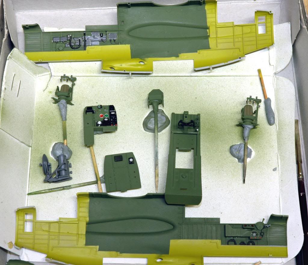
front of the engine nacelles - i have glued them already - there was a space there too!

cannon bay - its open with 4 long cannons and no room there

in front of the CG - yes true, but there is another side to adding more there in available areas.

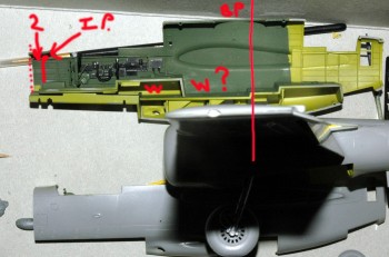
Please excuse my crude drawings!
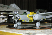
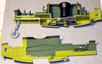
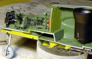
I've lined up the wing to the fuse join position so you can see the CG, red line vertical is about it.

you can see up front where GWH shows you to place the nose weight - #2 is the space they give, dotted line is the radar bulkhead, and IP sits where the short red line is.

55g of lead to fit there...... :rotf

W is where you could pack in the lead, but I suspect being further back to the rear just how many extra grams of lead would be needed!.


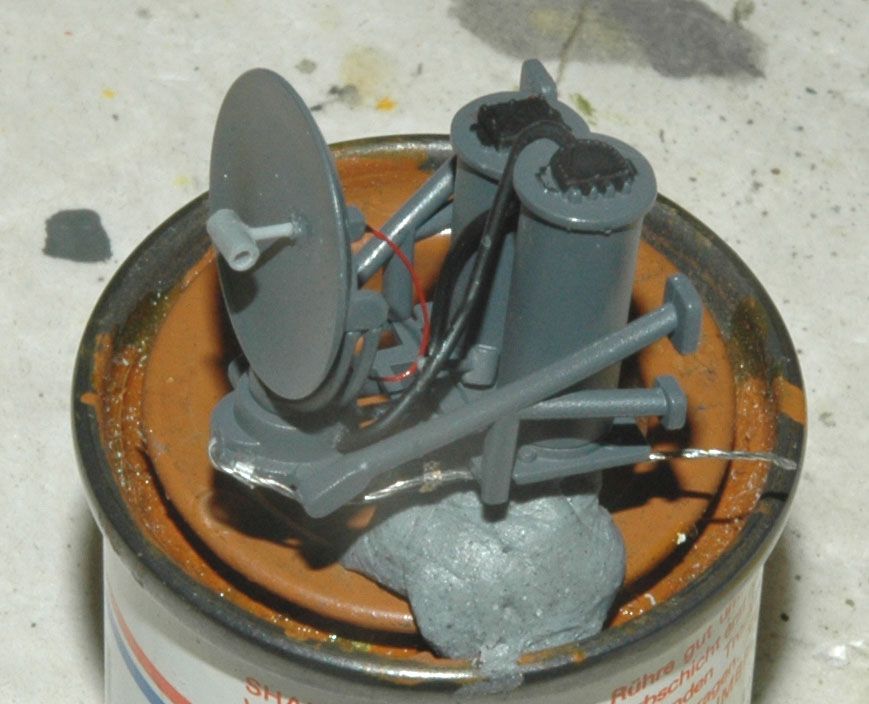
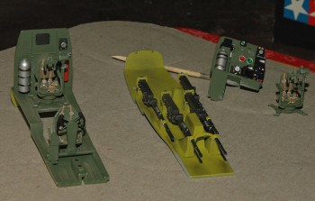
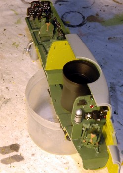
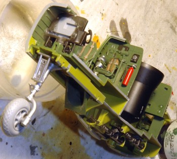
Here are the main gear leg attachment points - two small pins X that go into precut hollows in the bay,the arrow points to a glue join, and believe me it's not that strong!

1 is a point where I intend to apply glue for a bit more strength - not shown by GWH as a glue point.


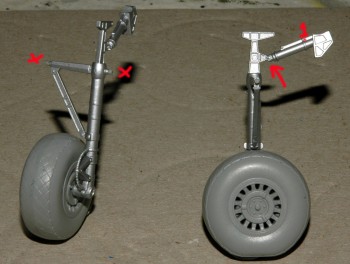
here you can see just how tiny those attachment pins are, I am thinking about replacing them with brass tube for more strength.

This is also adds fuel to the fire on just how much added weight these would take.


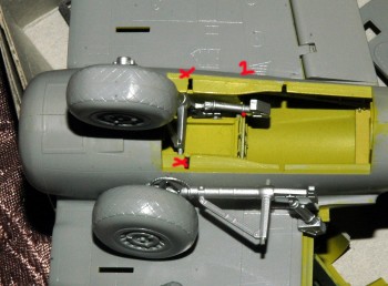
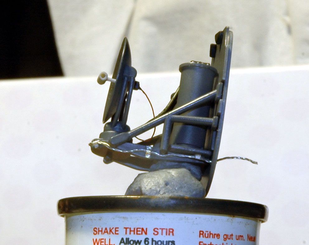
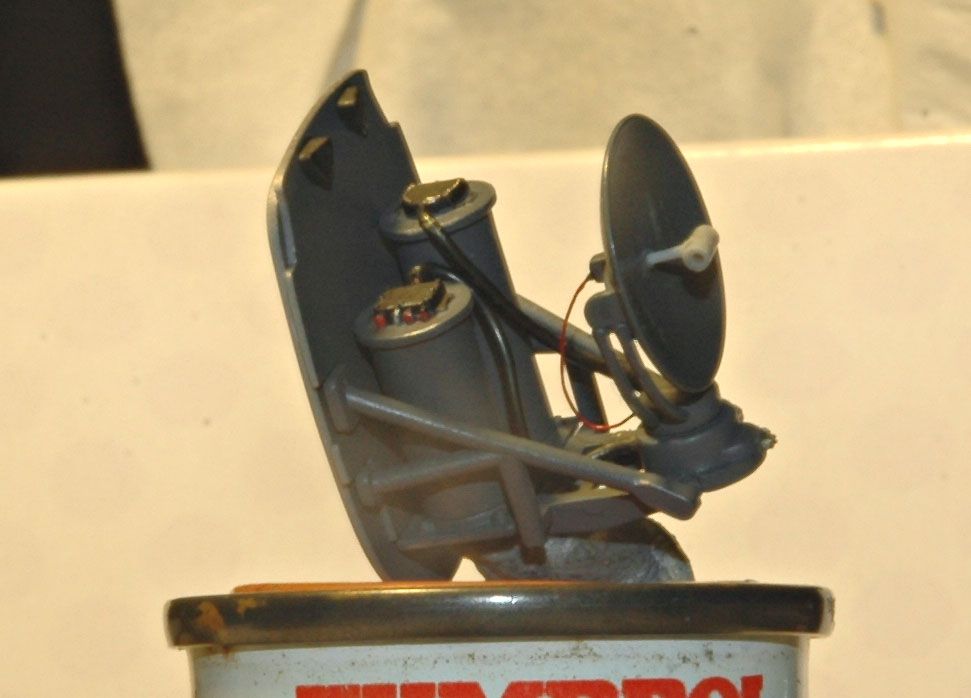
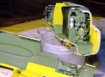
the dotted line shows how critical the fit needs to be when gluing in the gear bay, my mistake here was not aligning it with the other nacelle half dry fitted to check before the Ca glue hardened, will have to add a thin piece of plastic to cover the dotted line area and give some strength to the exposed pin


front wheel attachment points are not much better, again four small pins to support the weight, and I did glue that front support plate wrong - fixed now


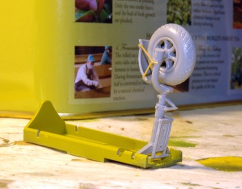
I think if I added sufficient weight to the available areas the model would weight a tonne! so my thoughts of a small dio board with the three wheels fixed is looking good to me at the moment!

have ordered this, which I will set in a picture frame or make up a smaller board like my large ones.
http://www.bnamodelworld.com/aircraft/aircraft-aftermarket-sets/for-aircraft-1-48/tarmac-display-base/1-48-psp-coloured-pre-painted-model-pad-400x300mm

which I think will look rather good with some modelling sand scattered over it and a few added extras, jeep, figs etc.
 
Hmm...might want to put it on a base and screw it down. wonder if you can add any weight inside the nose wheel itself??
 
Depleted Uranium might work MP.......!!

I played around with weights today to see just how much it would take - gave up once it started to droop in various places - the mask tape wouldn't hold it together!!

It will be fixed to the board, so the weight prob is fixed for now.

Started the guns - the two 20mm on the left are just black basecoat, right two have been ''metalized'', the 50 cal has just been started
 
well finally some enjoyment - a bit anyway.
This chinese plastic is bloody pathetic, while fixing the 20mm cannon in the bays tonight the front support just broke for no reason, at least it made fixing the guns in a bit easier.


not really much progress, the Pe belt set is one horrible set, like the plastic is breaks without warning.

The super detailed engine Pe piece is something I just can't describe - try bloody impossible to fix - even thread into the double row cylinders of the engine.

I'm hoping Hobby Boss kits are not the same as this GWH kit - plastic wise.
 
My lighting screwed up tonight, the yellow shows very harsh, so just discount that.

pit, guns, radar op compartments in now, I'm not bothering with more weathering this thing inside, each time you bump something it breaks.


This has serious fit problems when attaching the port fuse section, the 20mm guns need to be threaded thru the gun holes and an act of contortion need to align the two halves -( wait! - there's another part just broken as I do this...... )

By this method? of chinese engineering I may have to dry fit the two halves first, even then they don't sit together thanks to misaligned pin and hole locations, then add the glue in sections to get the deed done.


the ip gives three sliders with no levers??? so added leftover Pe levers, guessing they are for the landing gear.


the ip - all those dial decals are singles - what a nightmare to - each one needed trimming right to the dial, otherwise the oversized clear backing looked like a dogs behind on the panel.

All detail painting with Humbrol enamels


the front gear leg and access hatch must be attached at this stage, the gear leg is trapped between the gear bay and fuse side, access hatch by the gear bay and pit floor - another pain as I had glued the frail thin ladder to the door - as per instructions - how it was to survive masking and painting is beyond me - so I drilled out the glue holes and freed the ladder, for some insane reason it didn't break :yahoo:


that front gear leg now has a Ca glued long brass rod inserted inside it now and thru the gear bay floor - that sucker should hold!
 
Looks great! have you looked into Terry Dean's nose weights? He has a set for this kit for a couple of bucks.
 
Thanks Chuk , this needs 55grams to just hold this down, but with the glassnose there's not much space to try to fit a minimum 55g to it, the space that GWH shows to fit a weight is in front of the IP and the rear of the radar bulkhead =

What's my options - I could omit the radar dish and paint the glassnose to add the 55grams up front, but then that defeats the glassnose version I bought

or pack lead into any available space - this would make the model as heavy as a house brick !

The gear legs would not survive all this weight I believe, even brass pinned I have a feeling this still would be a problem with it.

The gear legs will need to be repined with brass rod in any event, I read a build of the first release and the builder recommended doing this as his main gear legs collapsed when the model stood on it's own.


The finished model will be secured onto an Eduard PSP board by inserting brass rod Ca glued into the wheels.
 
Back
Top