• Modelers Alliance has updated the forum software on our website. We have migrated all post, content and user accounts but we could not migrate the passwords.
    This requires that you manually reset your password.
    Please click here, http://modelersalliance.org/forums/login to go to logon page and use the "Forgot your Password" option.

Wingnut Wing SE.5a

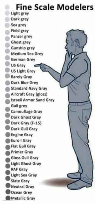
Nah, this is the scale he needs.
Colors to Modelers.jpg
 
Rigging and attachment points.
I had gotten the RAB Productions RAF Wire set years ago for the SE5 and after looking at the suggested instructions it appears you have to have the kit built up and measure what you need then cut. I'm not a measure twice, cut once type guy so I'm not going to try that. Besides the wings might be a bit wobbelly between measure and fit so nope.

On the Tripe I used this white flat elastic thread someone suggested and it worked out great to the best of my memory. It actually flattened out because the pivot of the attachment point sort of pulled it flat, I was careful to make sure I didn't twist so they still appear to be aerodynamic.

But the attachment points have been bothering me so I hit up Gaspatch.

Y'all see that I got several different styles for RAF types, the metal ones just kinda confuse me. It has a rod protruding from the nut, the instructions call for you to put a pipe over that rod with the rigging material strung trhough the pipe. This makes the rigging line offset of center of the attachment point. Will we notice? I don't know but I see it!
1790456513114.png


1790456560203.png


They have these nice 3d printed attachment points that have holes down the center. It really makes more sense.

1790456600873.png


You can actually attach the lines in the holes with these attachment points strung and then put them in place secured with CA.

I also played with pre threading them while still on the runner.
1790456684375.png


Yes, gotta drill out the hole a bit but that's not a biggy if you got a thin enough drill or even wire.

These are the ones I'm going with! Hope there's enough but we'll see.
 
I ordered some 3d printed ones as well but decided against as they are very weak and i though they might just snap when i tension the wire.. In the end i made my own, they were not technically correct but they made all the right noises :rotf to the casual observer.
 
The anchor points will not hold any pressure, they are purely cosmetic. You drill hole for the rigging material then secure that, then you can slide the anchor in place.
With the metal ones I don't understand, did Gaspatch expect us to drill a slot for that shank to fit into?
 
I think that flat shank is supposed to represent the plate that some aircraft attach the rigging to. Here are some resized photos from the Air Force Museum. Hope they help.
Spad XIII

Spad XIII.jpg


Spad XIII - 02.jpg


Spad VII

Spad VII.jpg


Nieuport 28

Nieport 28.jpg


Sopwith Camel

Sopwith Camel - 01.jpg


Sopwith Camel - 02.jpg


Sopwith Camel - 03.jpg


DH-4

DH-4.jpg


I am sure that some of these are reproductions and should be considered accurate since they are part of the Air Force Museum. Others are restored and as such are also done as well as can be considered. They had an SE5a, but it was hanging from the hanger roof so without a telephoto, I couldn't get more than a couple of "Here are SE5a photos". It looks like the British fighters all had "flying wires" which are airfoil shaped solid wires with threaded ends that adjusted with the clevis on the end. The DH-4 had cables as well as the French planes. The French planes had double cables going from lower to outer upper mounts that were connected and wrapped to make a single airfoil like support.

Hope these help.
 
Thanks guys, yes the flat part is the attachment plate that the anchor secures to. Those plates can be sized to fit. Carefully of course.

From what I have read the flying wires are in essence turnbuckles themselves. The flat elastic string will represent the aerodynamic flying wire.

1790550933776.png


Medium Grey out of a Model Masters jar.
 
Back
Top