• Modelers Alliance has updated the forum software on our website. We have migrated all post, content and user accounts but we could not migrate the passwords.
    This requires that you manually reset your password.
    Please click here, http://modelersalliance.org/forums/login to go to logon page and use the "Forgot your Password" option.

A G3M2 Nell in 1/48 the hard way

Wow Gary! While I have a number of Vac kits in the stash I have only tried to build one, a 1/72 scale HL-10 lifting body. My biggest problem was lack of reference for the cockpit and wheel wells. The kit was crisply molded, but with no real info it finally just got set aside. Should go on a jag and try and finish it sometime. Have the skills now.

Will be watching with interest! :popcorn (y)
 
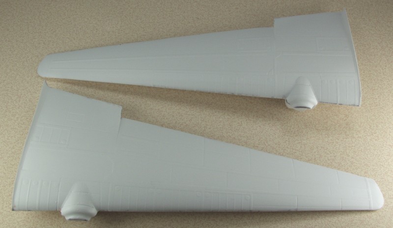
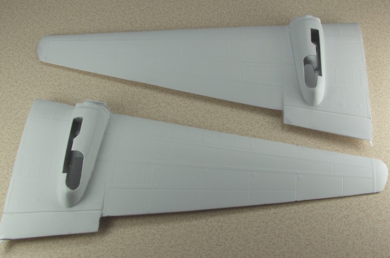
At this point I have finished freeing all of the white parts from their molding sheets. The lower wing halves have inserts that box in the wheel wells and provided indentations where the holes needed to be drilled to mount the landing gear. The insert was fairly thin so I added some .060" styrene before drilling out the holes to provide a more solid mount for the gear.

g3m2-b10.jpg


The fuselage halves were joined. The basic vacuformed wing spars seemed a little flimsy to me so I again added a .060" styrene stiffener to them before installing them in the fuselage. I had a bit of seam work to deal with but over all I have had worse on some injection molded kits.

g3m2-b11.jpg


g3m2-b12.jpg


The wings have been assembled minus the ailerons as these are the flying type like used on the Ju 52 and other Junkers aircraft. Mitsubishi got some of their technology from Junkers in the mid 30s. They will be left off till the very end to save constant repairs.

g3m2-b13.jpg


g3m2-b14.jpg


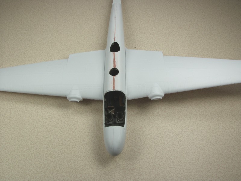
Here is a test fit of the wings to the fuselage. I haven't done anything at this point to improve the fit but am quite pleased with the fit so far.

g3m2-b15.jpg


I will not be mounting the wings until I get all of the clear parts fit as I may need to use the fuselage as a guide to contour the fit on some of them.

The engines and cowlings will be the next challenge. I had hoped that the very thin material of the cowlings would allow me to avoid the Vector engine curse but alas it appears that some grinding on the tops of the cylinders will be required for fitting here as well.

Thanks for looking !
 
OK, still working on this one but the C-123 for the cargo campaign has been stealing me away some.

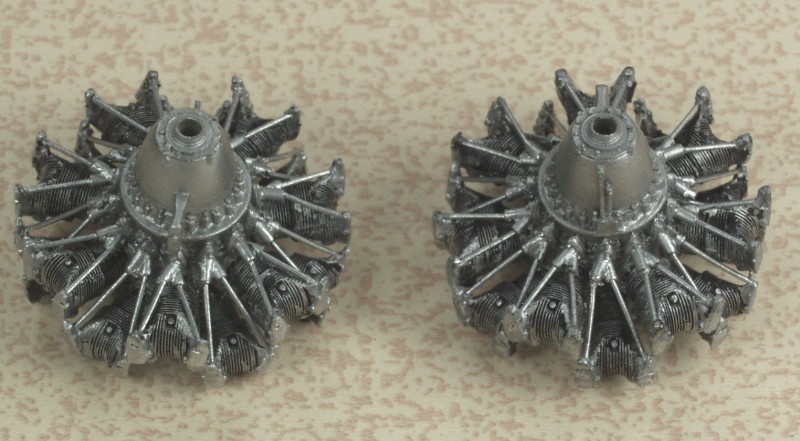
The Vector engines consumed more time than usual. I only had to grind away about half of the rocker covers to get them to fit the cowlings, I have had to do much worse to others. The push rod tubes guides near the crankcase were a major PITA to clean up and install due to their small size and the made the push rod tube installation a major aggravation as no two end up the same length. I finally ended up drilling a hole through the rocker covers and down and into the guides and inserted them from the top and trimmed them flush. Tedious but easier than trying to measure and cut each one.

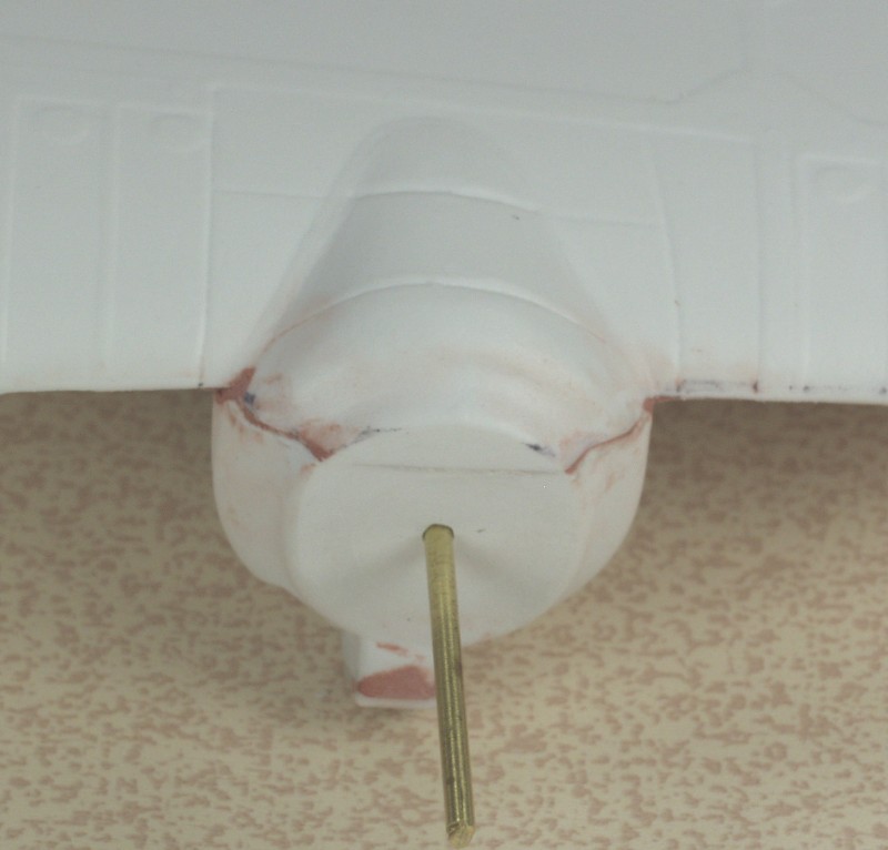
One of the crankshafts had broken off in shipping and both appeared to be too wimpy to support the cast metal props. The props themselves had a rather beefy shaft as part of the casting and drilling a hole that large in the front of the crankcase looked to be a disaster in the making. I end up drilling a 1/16" hole through the engine and cutting off the prop shaft and drilling it out the same size. The area where the engine was to mount had no alignment devises but there was a small dimple in the center of the area so I drilled it out to 1/16" as well. That way my new prop shaft, some 1/16" brass rod, would pass through the engine and into the mounting area correctly positioning the engine. I have secured the brass rod into the cowling but the engines and cowls will be left off till after painting as they will be black it will save masking them.

The engines...

g3m2-b16.jpg


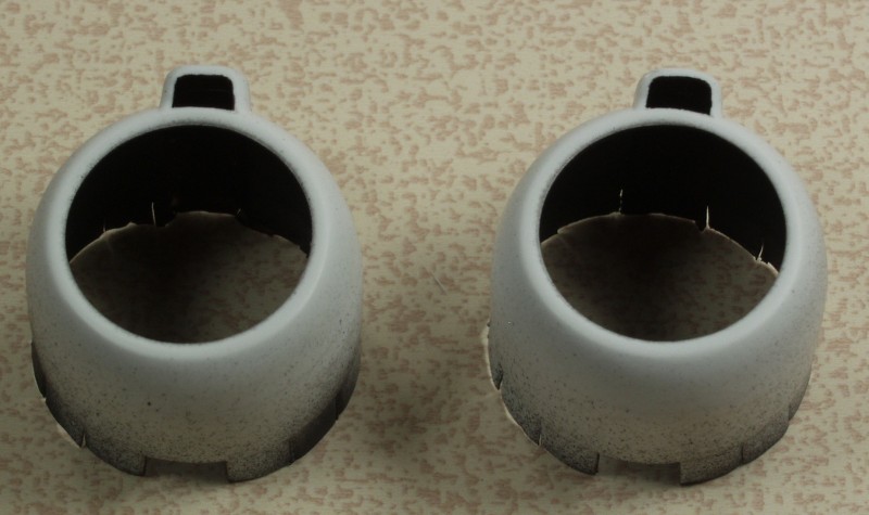
The opening in the cowls were cut out and the insides painted black...

g3m2-b18.jpg


And the prop shaft/engine mount...

g3m2-b17.jpg


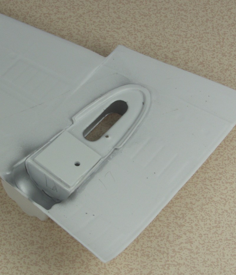
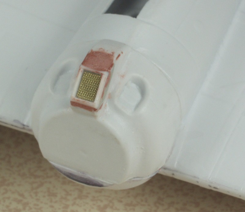
One of the issues sometimes encountered with vacuform kits are areas where the plastic when it is formed over the mold gets stretched to paper thinness. On this kit this occurred on the cowling part that is under the wing. There is a scoop there for the engine oil cooler and the area was so thin that it crumpled when you tried to do anything with it. To deal with this I used some Magic Sculpt, similar to Milliput, and filled in the area behind it forcing the area to take the shape intended. When it had hardened I was able to sand and shape the area as needed but it left me with just a flat area where the opening as supposed to be and no easy way to make one without carving away at the Magic Sculpt. While looking through my supply of styrene I found I had some very small 1/4 round stock. I used this to form an frame around where the opening should be and then used putty to fair this in. Once that was done I cut a couple pieces of 100 x 100 brass screen to simulate the oil cooler. Not sure how close this is to the prototype as the photos I have this area is in the shadows and difficult to see but it works for me...
g3m2-b19.jpg


Still need to get all the clear parts to fit and masked and then the wings can go on but I need to finish the 123 first. Thanks for looking !
 
I know exactly what you mean about radial engines. A real PITA most of the time ' :blink

Congratulation on your progress. :good:

Cheers, Christian B)
 
Just caught up with this thread... amazing work Gary... I looked at a vacuum form kit, once and sat down until the urge passed.
 
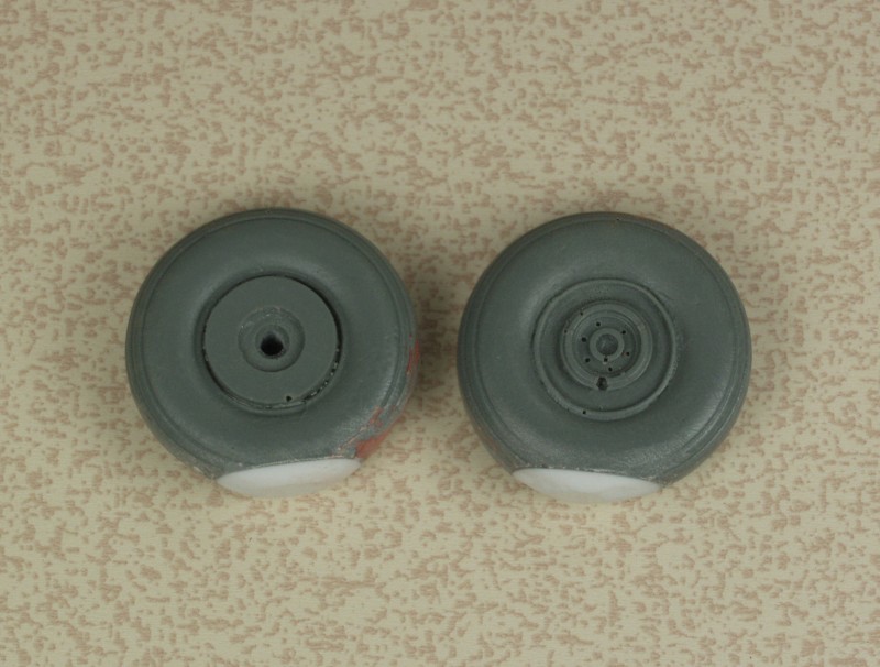
OK, just some bits and pieces for today's update. Finishing the C-123 took up a lot of time of late but I'm now back on this. First up the wheels and tires, the tires just looked way too flat to me so I glued on a block of styrene on each and sanded them to shape, much better to my eye anyway...

g3m2-b20.jpg


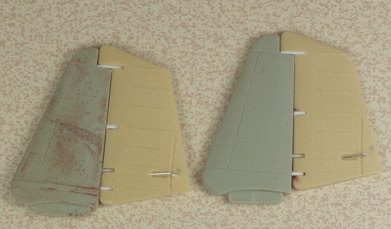
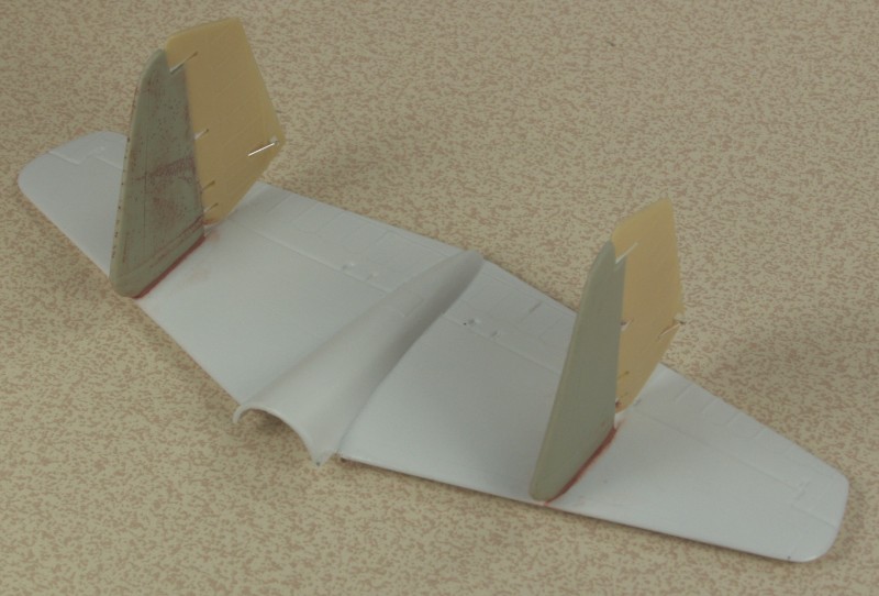
Next up I assembled the vertical tails and rudders. As can be seen the one vertical tail was a veritable piece of Swiss cheese with all the bubble holes in it while the other one only had a couple. Several of the rudder hinges were broken off and the other just waiting to break off so I replaced them all with styrene.

g3m2-b21.jpg


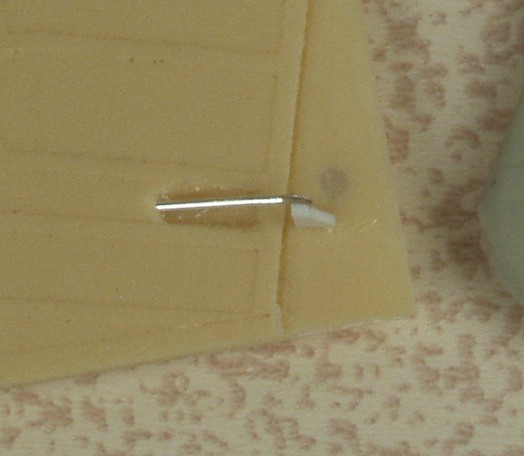
The rudders had a place molded in for the trim tab adjuster but none was supplied so I made them up with wire and a piece of styrene.

g3m2-b22.jpg


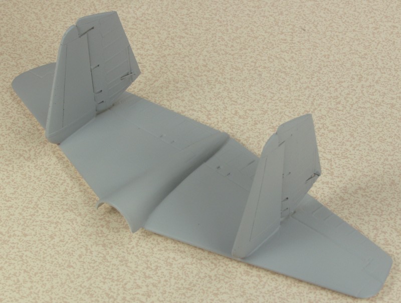
Once complete they were glued to the horizontal tail and fared in with some putty

g3m2-b23.jpg


And the assembly was given a coat of primer to check for issues before attaching to the fuselage.

g3m2-b24.jpg


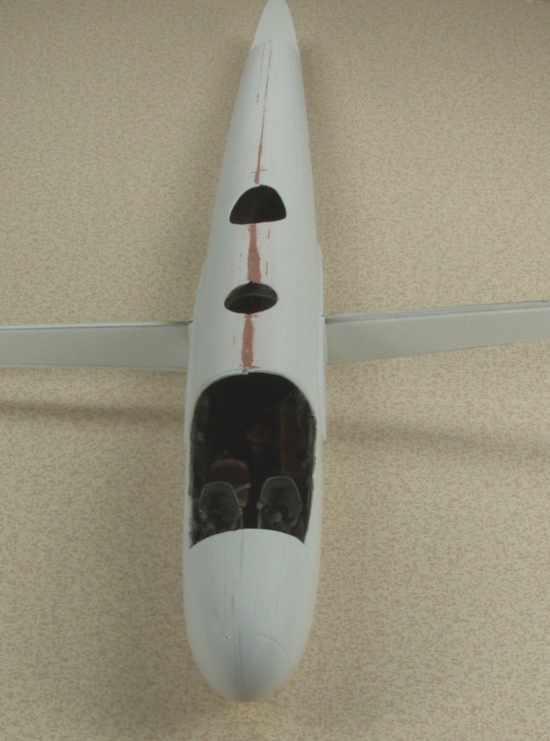
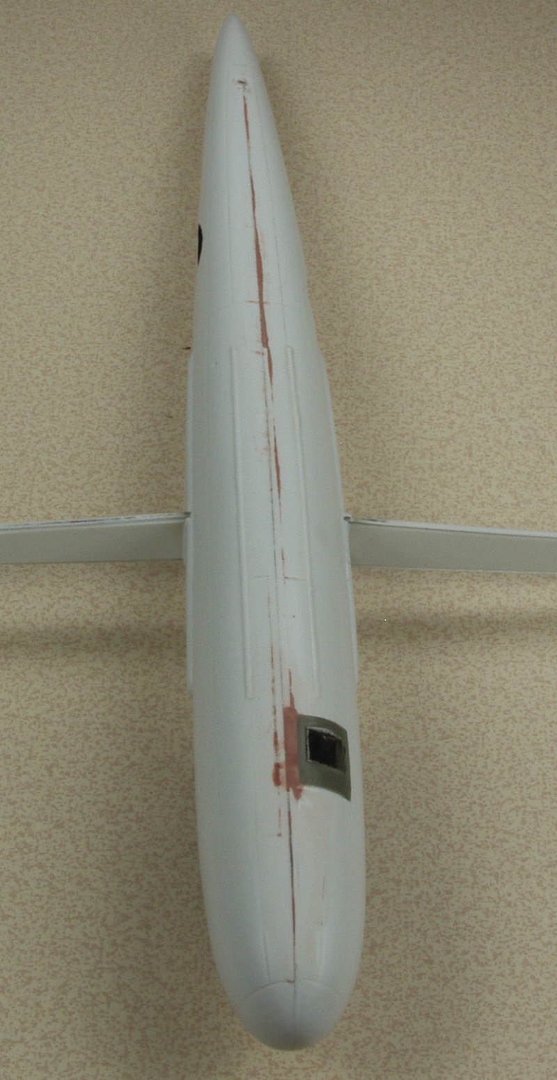
I have gotten the machine gun blisters cut out and shaped to fit the fuselage and Futured but masking will be slow and tedious with no mask kit.

More coming soon I hope, thanks for looking !
 
Back
Top