Well, I guess it's time for an update and my thoughts on the kit while I'm at it. So far what I've found is that for the most part the large pieces fit together well, not Tamiya for sure but not bad. The smaller bits not so well. I've found that though many parts have alignment pins, either the holes are too large or too small. A couple things I found irritating... The rear cargo door has no option for mounting it closed. There is nothing to hold it in place. I will probably end up gluing it to one half of the fuselage before gluing the halves together. It was also not shaped quite right but because of the softness of the plastic I was able to bend it a bit to fit. Irritation number two was the clear parts did not fit well. I ended up carving or sanding some on almost every one. To make it worse on about about half of them the sprue attachment points overlapped the mounting ridge on the part and cleaning it out of the ridge was not fun. I mentioned above the softness of the plastic, this and some of the large sprue attachment points and the mold misalignment on many of the smaller parts made clean up a chore.
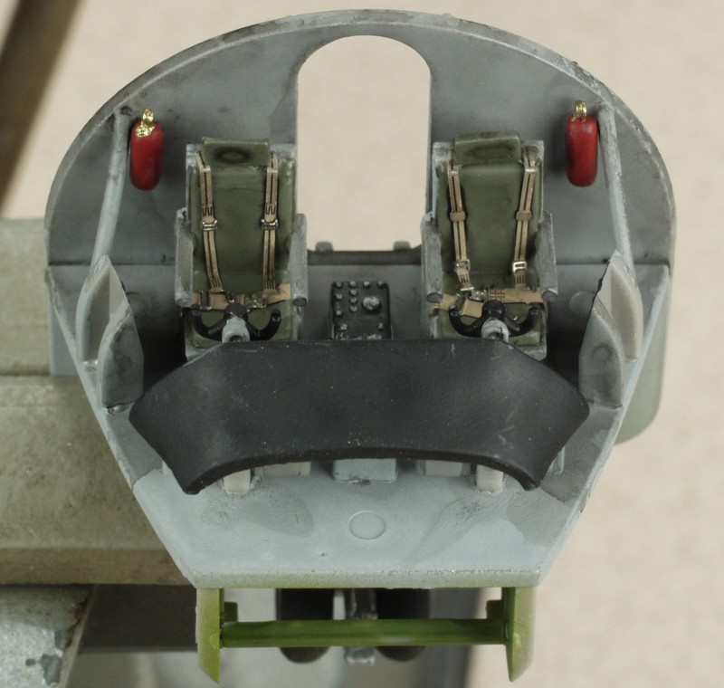
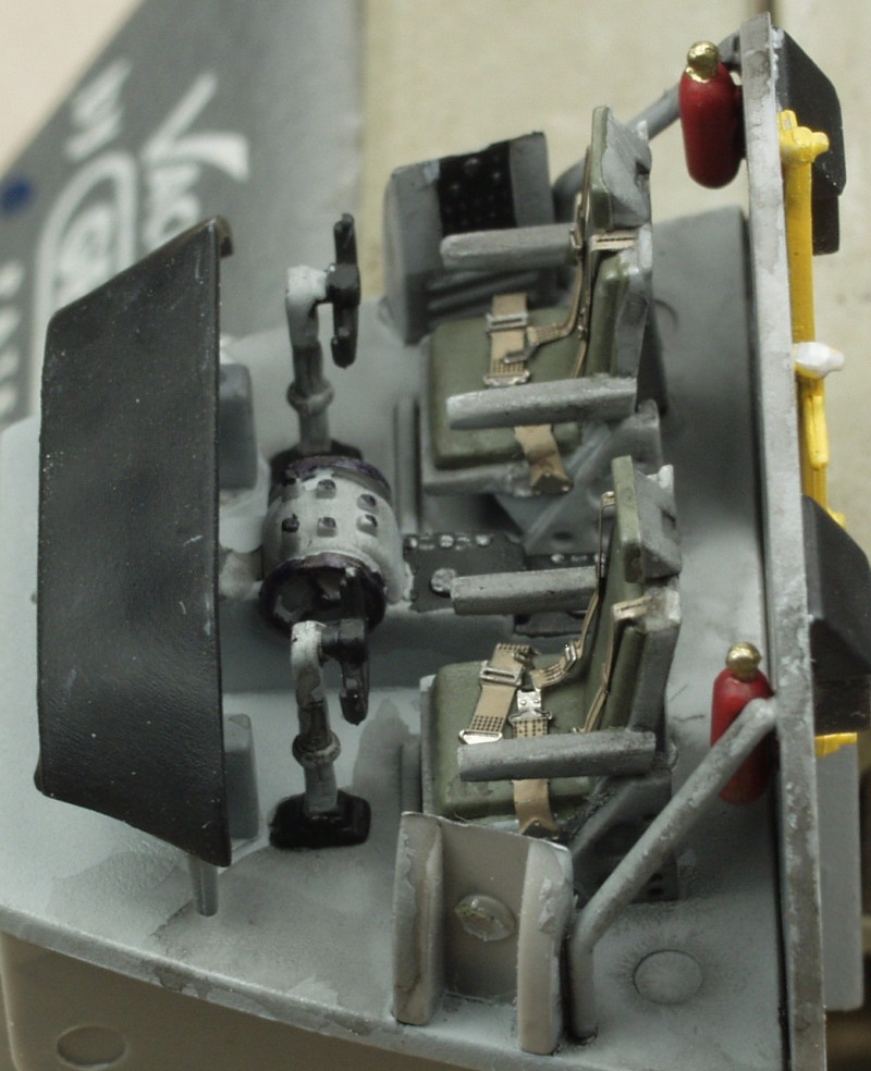
OK, enough venting. First up the cockpit, OK level of detail for 1/72 as far as I'm concerned. The canopy is not super clear so anything inside will not be all that visible any way. The IP is set back under the cowl and the indentations for the instruments were mostly too small for the instrument decals I had and the kit decals did not provide a panel so I just painted it black. I did add belts and harnesses to the seats.
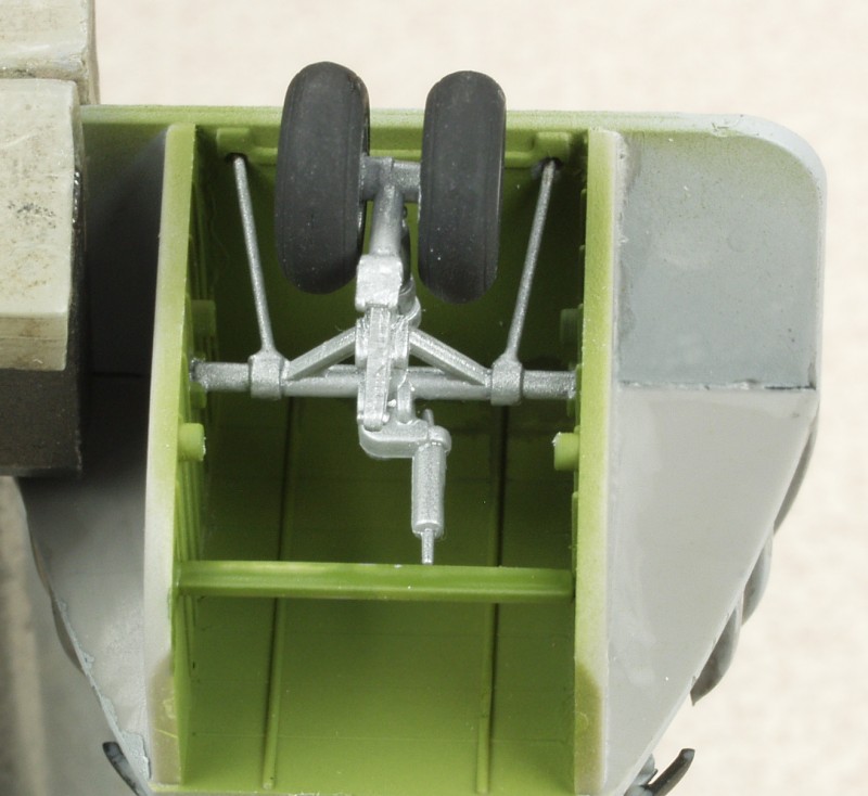
The nose wheel well is just below the cockpit and is part of the same assembly. The nose gear is pretty well detailed but about all you'll see in the end are the wheels themselves. I replaced the kit parts for the two small diameter struts with some brass wire as the kit parts were just too hard to clean up and make round. When I test fit this assembly in the fuselage I found there was an interference fit with the torque scissors but by clipping the tip of it off it provided an additional support point which is handy as the gear seems a bit wimpy for the task.
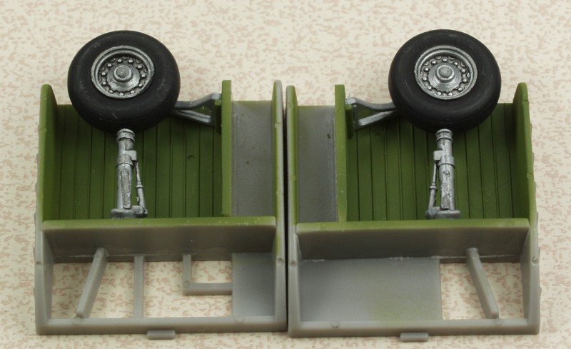
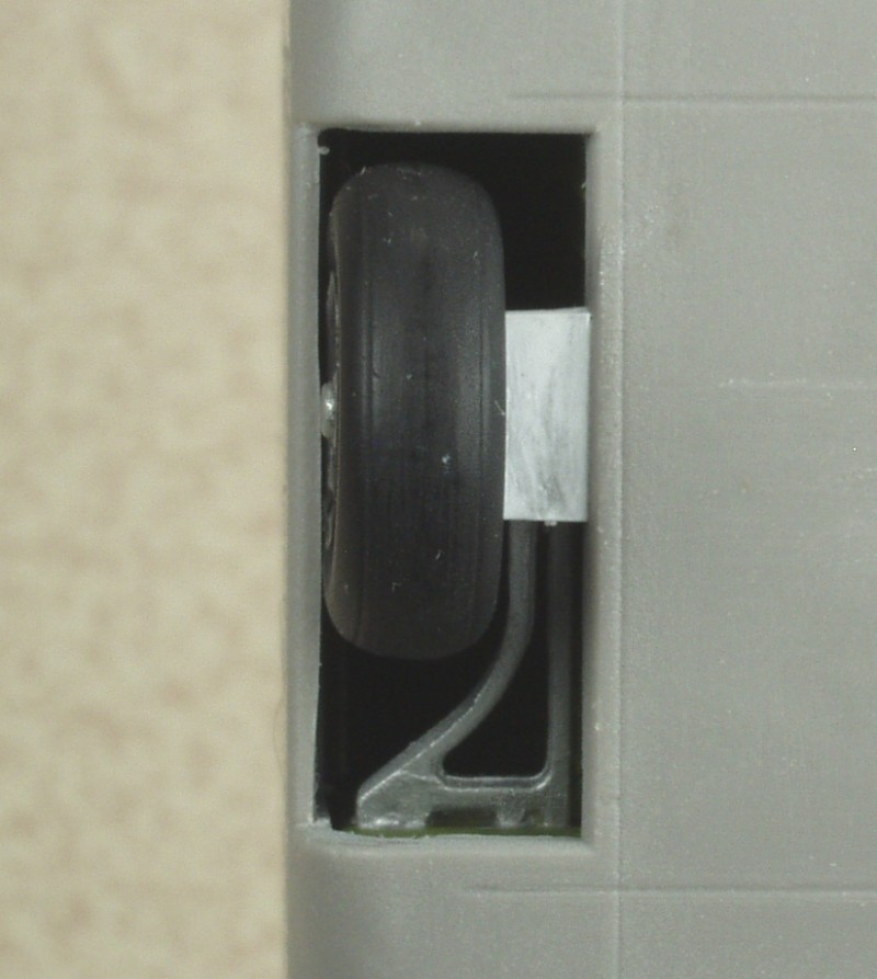
Speaking of the gear, the main gear are shown next. First off the wheels were a sloppy fit on the axles. I drilled them out, plugged the hole with some styrene rod and redrilled. As you can see in the photo the gear are quite long and have only a small mounting point at the bottom and a link connecting it to at the top. I reinforced the bottom point with CA and after noting how much flex there was also glued the top to the side wall for extra strength. This seemed to make them fairly solid but after mounting the gear bays in the fuselage I found when checking to see how much weight to add to the nose, that the axles actually flexed under the weight of the plane. Short of ripping it all apart and finding an alternative I resorted to gluing a block of styrene between the inside of the wheel and the fuselage. This seems to have strengthened ever thing so the wheels don't cant outward with the weight of the plane on them and painted black they will not be that noticeable. One can only see the bottom 2/3 of the wheel once installed.
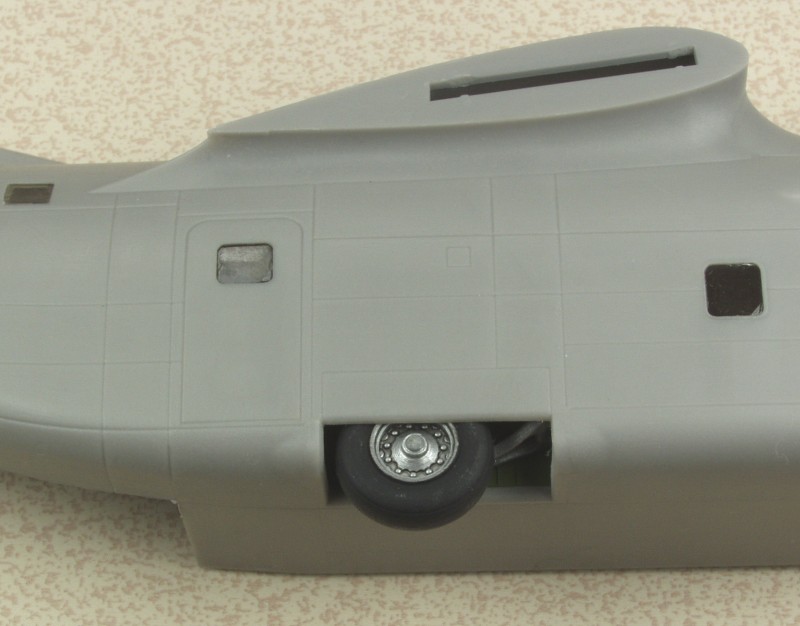
Also with the way both the nose wheel and main gear are designed there is no way to leave them off till after painting.
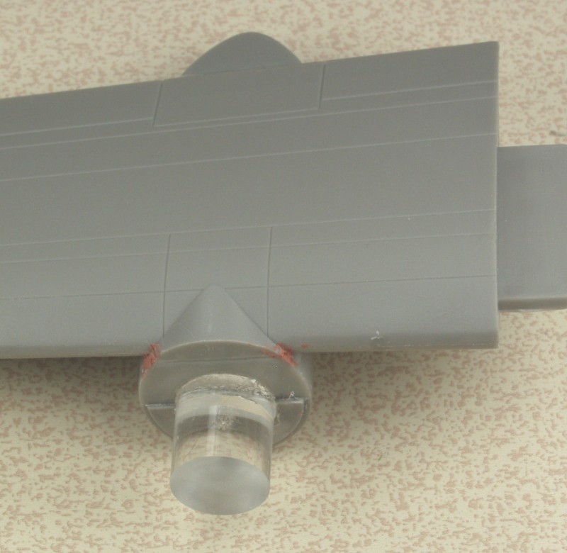
Speaking of nose weight, this thing is seriously tail heavy. The instruction say 40 grams in the nose cone. It didn't look like 40 would fit in the nose cone so I opted to put some behind the cockpit. Even leaving out all of the interior detail aft of the landing gear it took about 70 grams to make it a solid nose sitter. During this process I think I found why they want you to leave the back door open. It's the only way I can see that you could possibly align all the innards when assembling the fuselage. Since near as I could tell, none of the interior detail adds any strength to the assembly, I left it all out. Can't see it, doesn't need to be there !
The wings and tail parts were assembled, these went together with no issues, a little flash to deal with and some holes that need to be drilled in the bottom wing halves before assembly. I found it strange they provide the holes for the sway braces for the wing tanks but not the mounting holes for the tanks themselves.
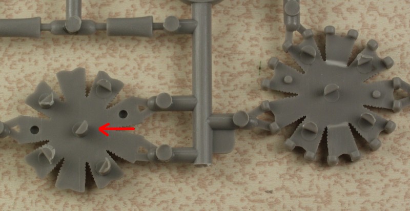
Next the engines. These go together OK for the most part with the exception of the engine accessory section which was poorly molded. It didn't fit well into the opening for it in the rear of the engine and the rear firewall didn't fit well to it. Unfortunately the rear firewall is the mounting point for the engine into the cowling. You can see in the photo that it is not sitting straight in spite of all efforts to make it so.
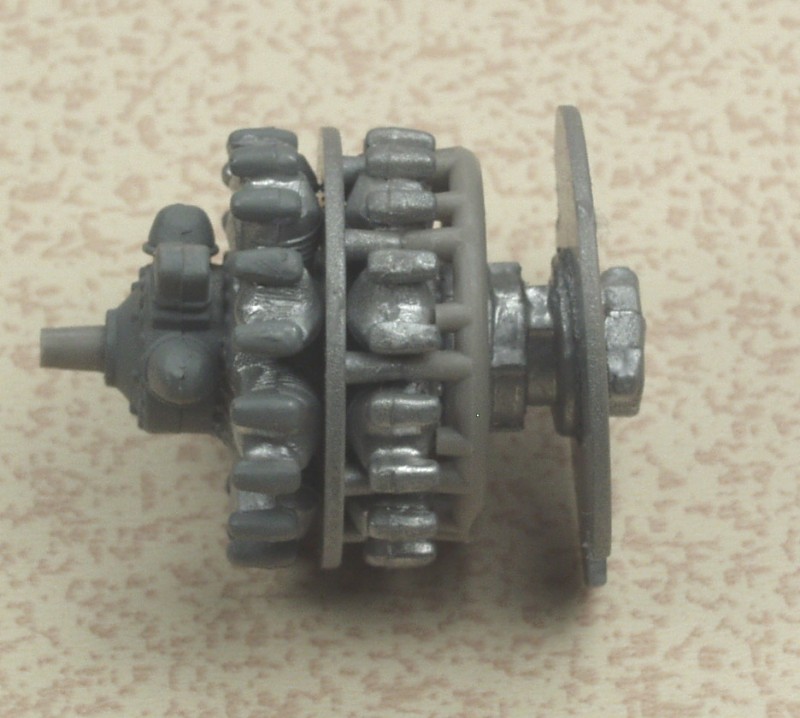
When I tried to test fit it into the cowling the first thing I noticed was that the two notches in the firewall were too small to clear the exhaust bulges inside the cowling. These were made bigger to get it to fit per the instructions but I found that this position left the front of the engine recessed too far from the front for proper fitment of the propellers. I tried to solve this by fitting it forward of the intended mounting ledge. This fixed the depth issue but I found I could not get the engine centered in the cowling. After I spent an inordinate amount of time shimming and fussing with this to no avail and came close to shoving the whole works back into the box. I finally walked away for while and conjured up another scheme.
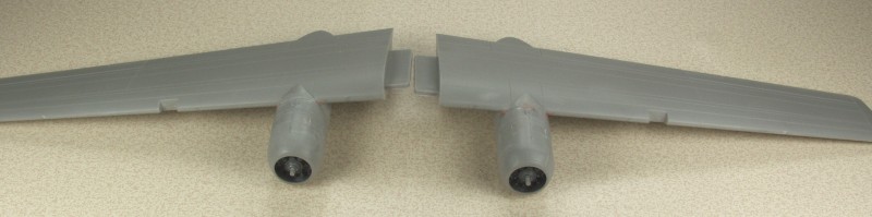
I cut the accessory section off even with the exhaust manifold. The manifold is still needed to mount the exhausts. Through trial and error I determined how long of a spacer I would need to attach the engine to the mounting point on the front of the wing. I had some 1/2" diameter plex rod in my material larder and I used it to make up spacers. When I found the right length I glued them to the wing as shown in the next photo.
The cowls were then glued to the wing and once set I put a big glob of slow setting tube glue to the back of the engine, set it in place on the spacer then attached the cowl front. Once the front was set ,I tweaked the engines into place then let everything set up over night. Finally assembly of the wings shown below.
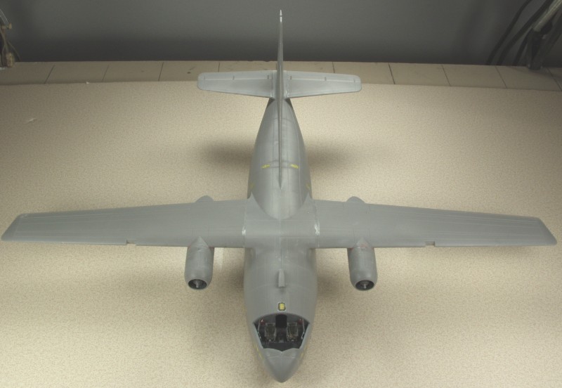
The fuselage went together relatively easy, I did it as a progressive glue to get each section aligned as well as possible before doing the next. I did use clamps in a couple places and the area around the rear door was the worst to deal with. I manage to break off the nose gear in the process but I'm going to wait till after the painting is done before fixing it. This is one kit that would benefit from some metal landing gear. After doing the worst of the seam work I glued the wings and tail on. The wings wanted to droop into an slight negative dihedral situation but checking drawings shows that it did have a bit of negative dihedral. Fit of the wings and tail was quite good. So that is where I'm at at the moment, a little body work to do before paint and I need to finish masking the main canopy. I really missed not having a mask set.
I know the above makes the kit sound like a real POS but it is pretty much typical for short run kits. I found this kit to be very similar to Special Hobby kits as far as fit goes. Just part of the joy of model building. I'm going to stop at the ready to paint point and finish my build for the Bomber Command campaign as it ends soon.
Thanks for looking !