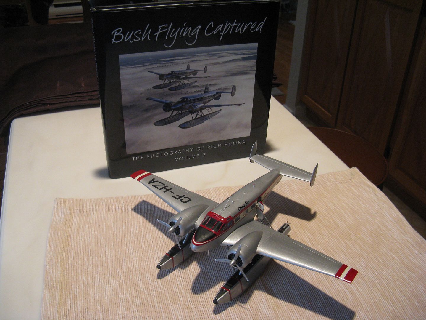
Thank you all for the kind comments, much appreciated fellas.
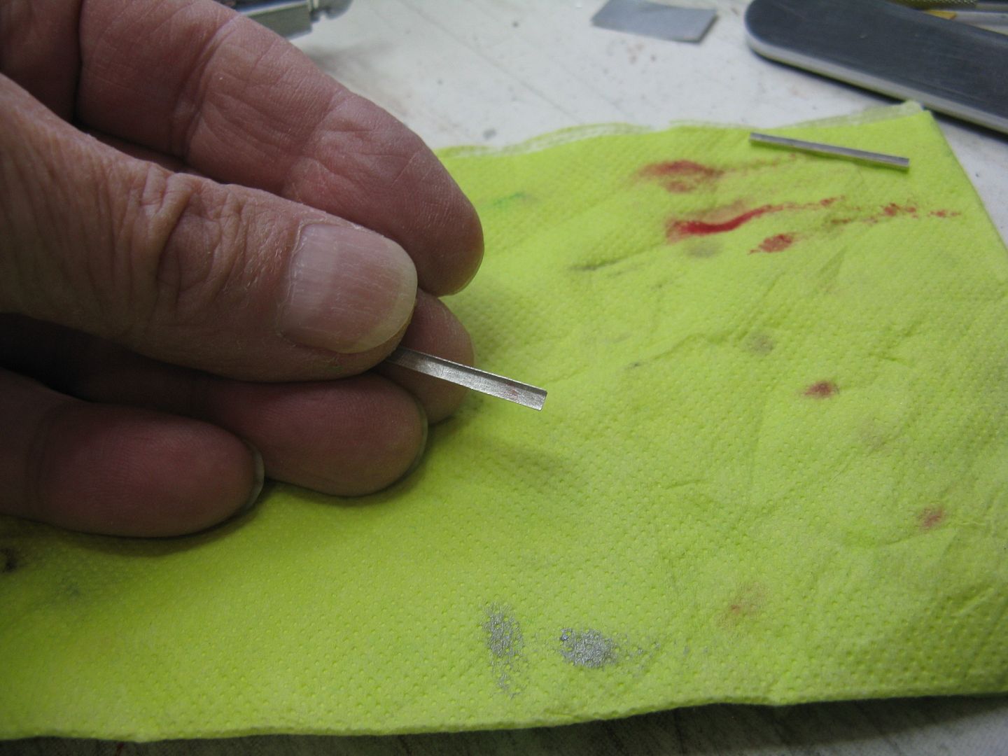
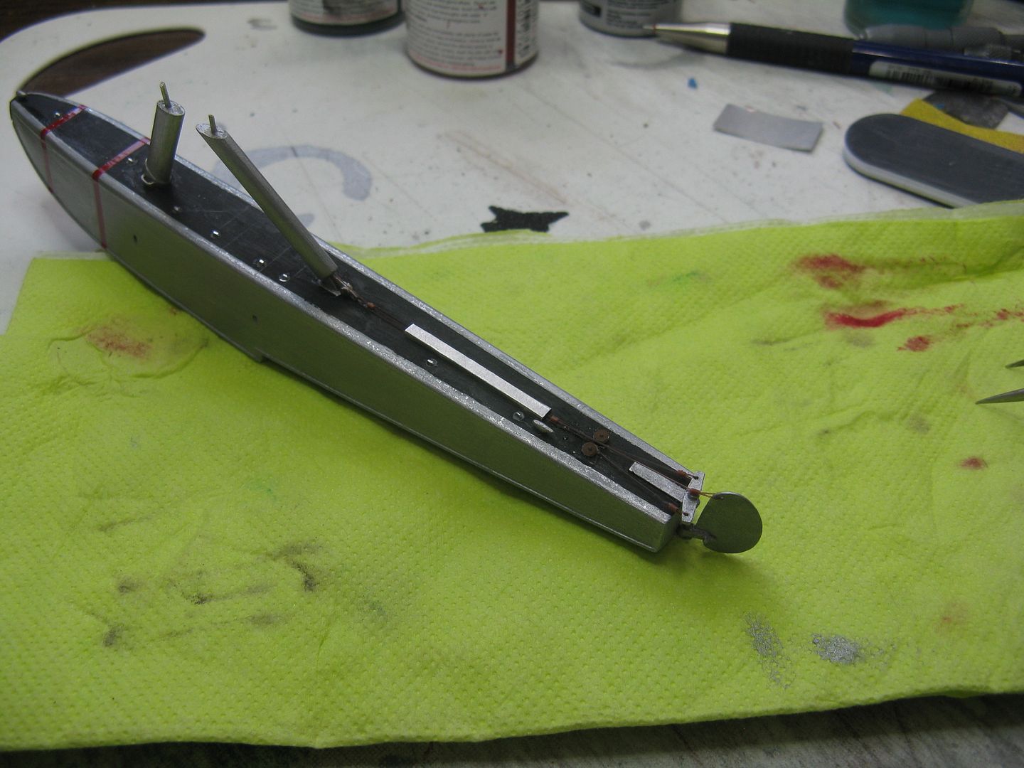
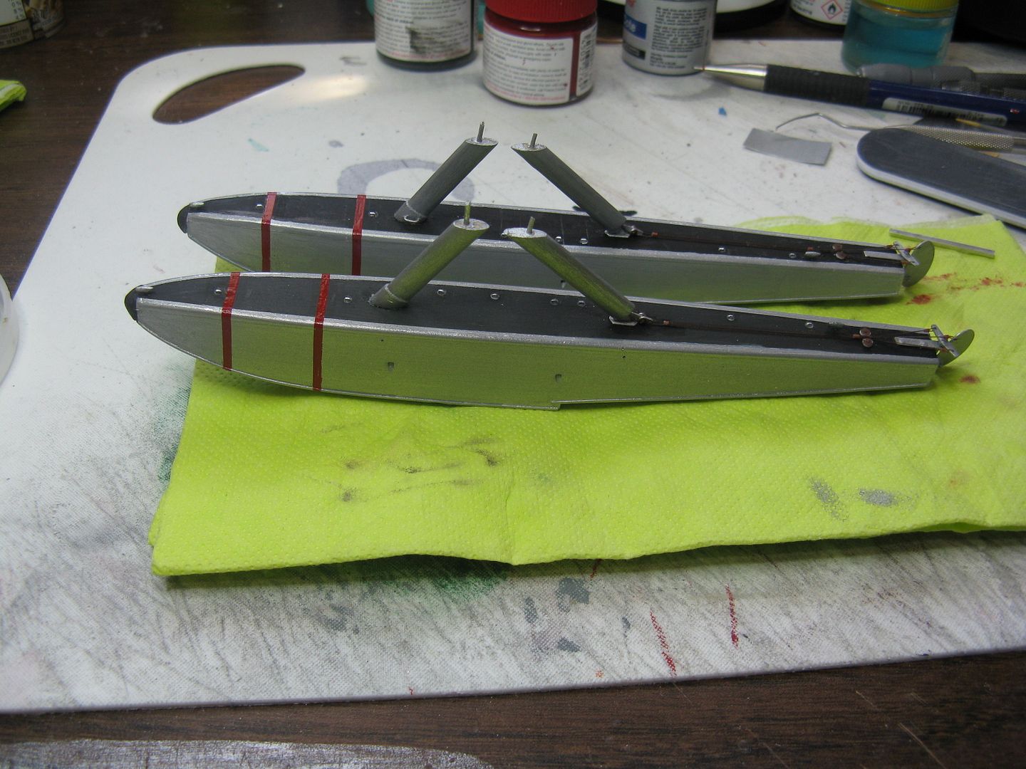
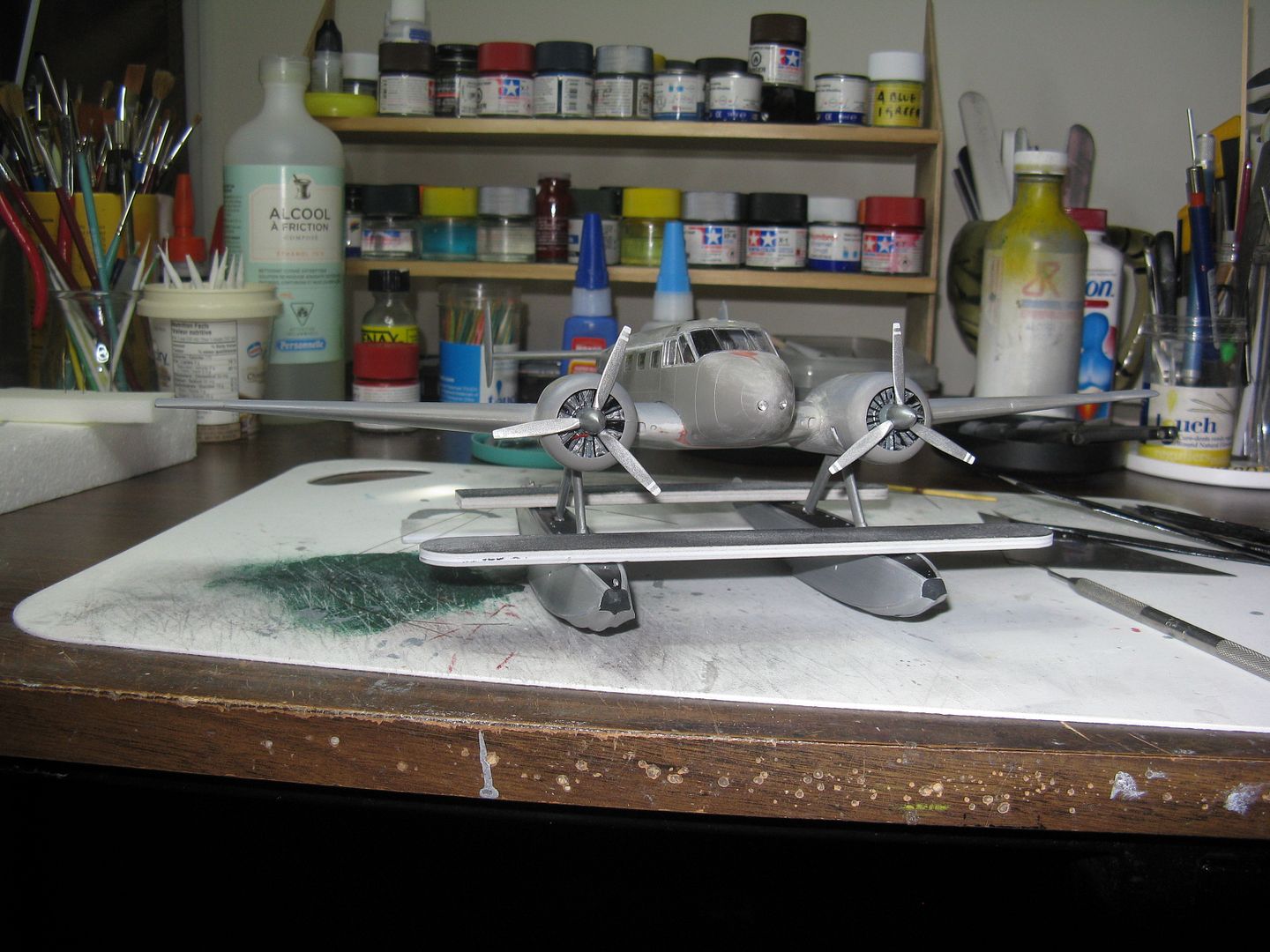
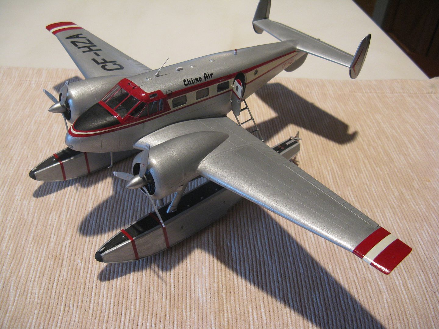
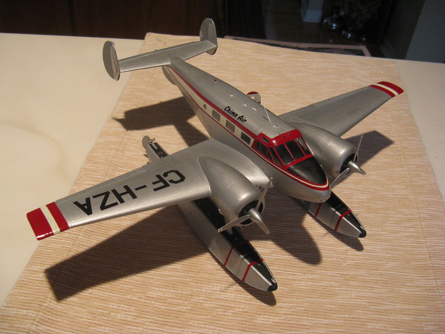
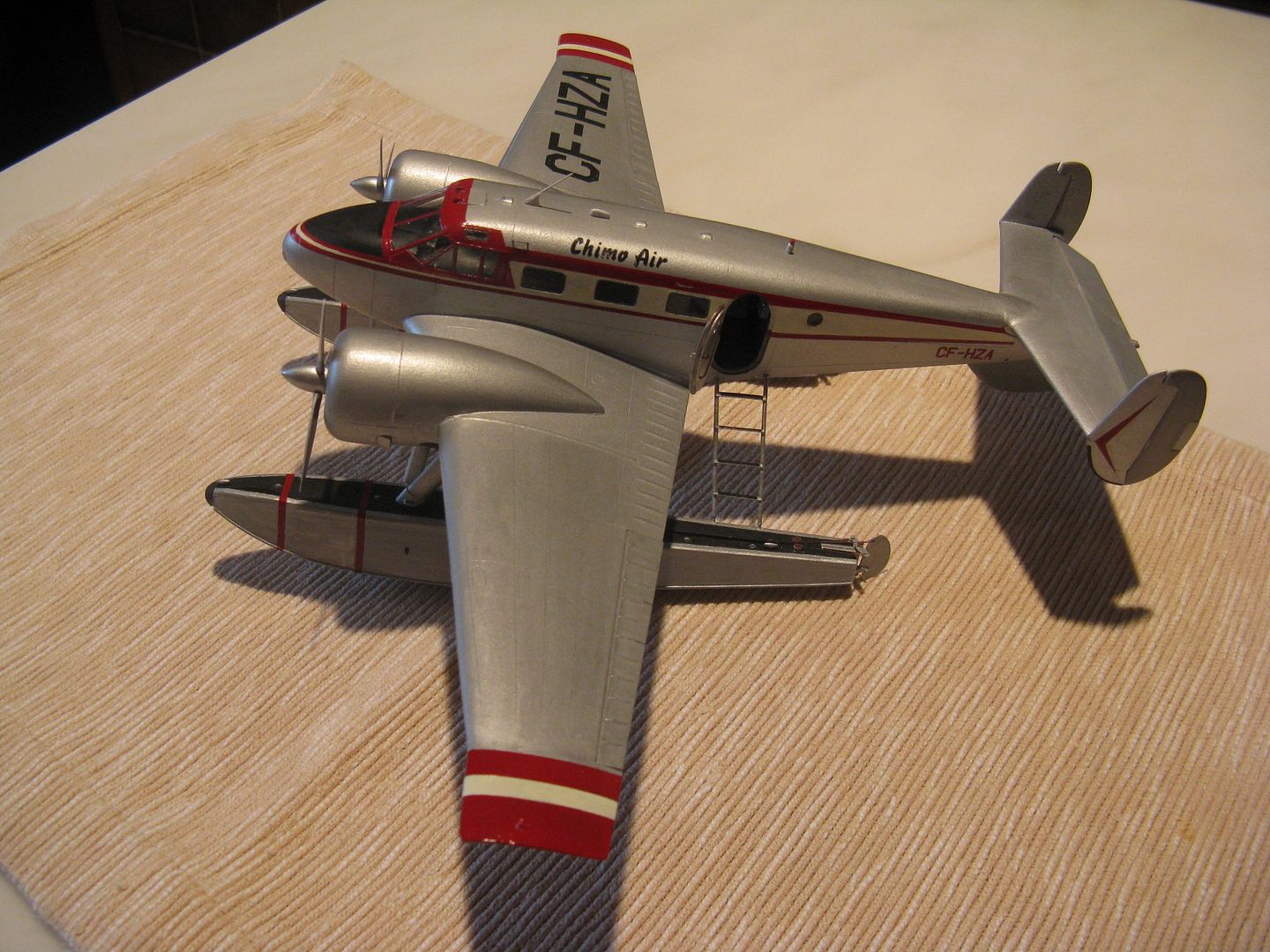
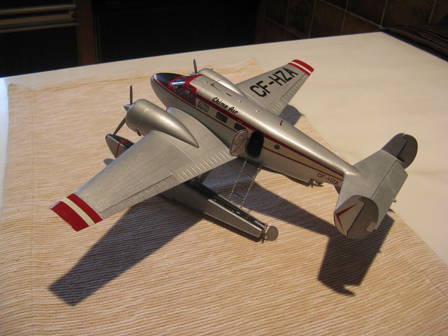
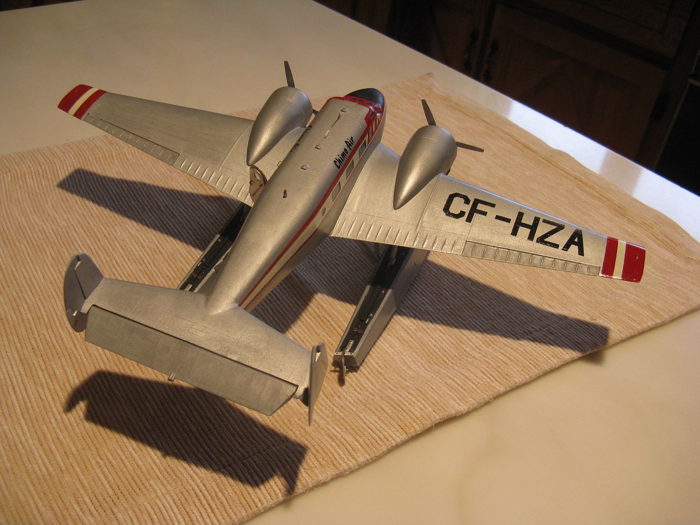
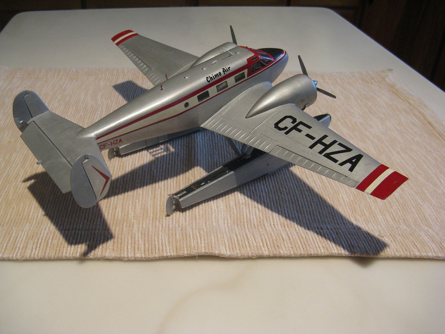
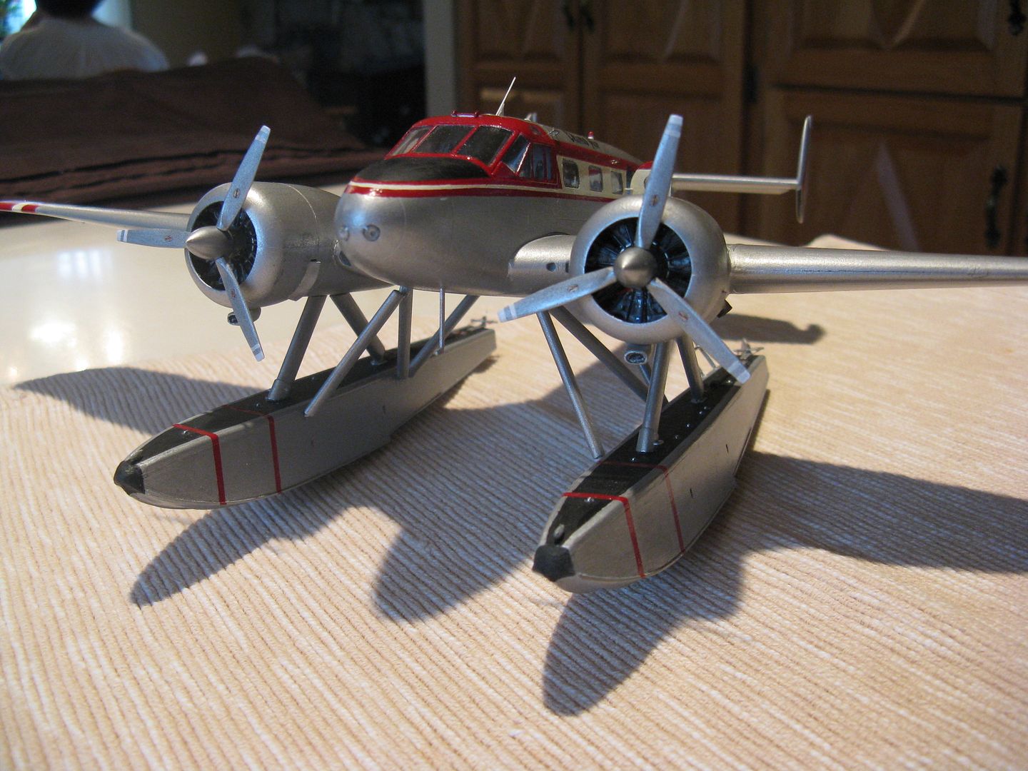
I have the floats and the main struts finished. The main struts are hefty affairs - as they must be - the airplane weighs what.. 9000 lbs? and the floats take a beating in rough water. I had no idea of the length, so I made the front one 42 scale inches, and with a 30-degree aft rake it gives around 38 inches of clear space between the deck of the float and the nacelle, at the lowest point. The front strut and the upper end of the rear strut are attached with a simple wire pin, but lower end of the rear one is more complicated. To begin with, the water rudder cables run up inside the strut to the nacelle, where by some PFM process they connect with the air rudder cables. This attachment called for some creative thinking. First, cut two funny shaped little fittings from scrap metal...
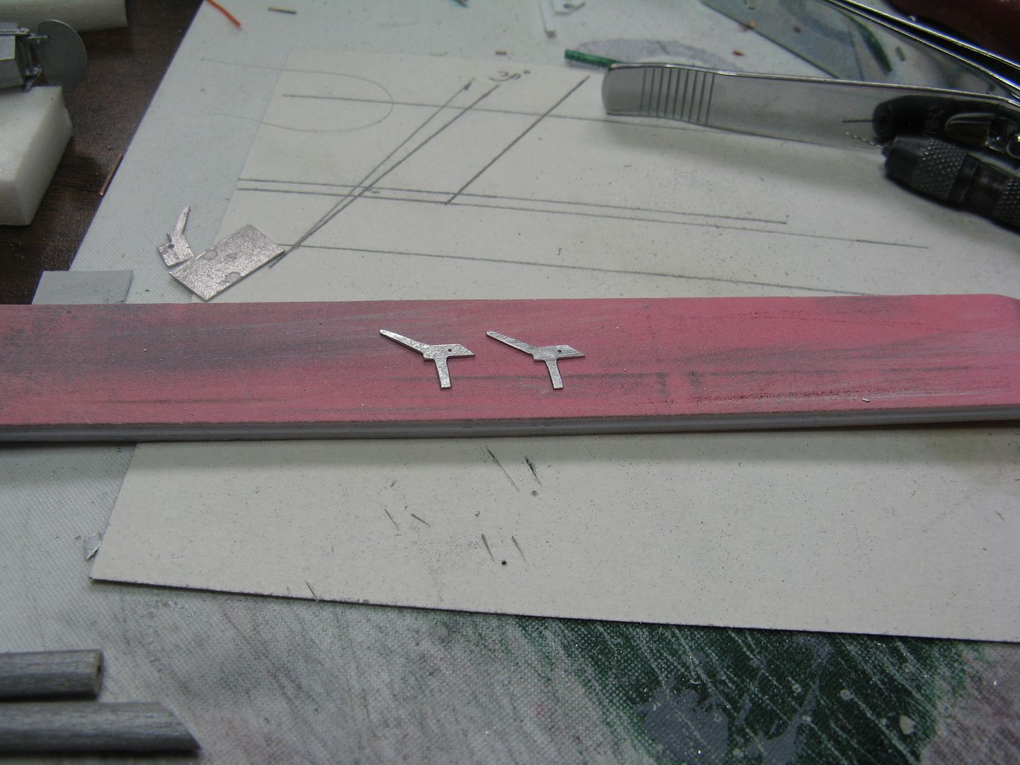
Then drill a hole in the lower end of the strut and shove the long arm of the fitting into the hole and epoxy the thing in place.
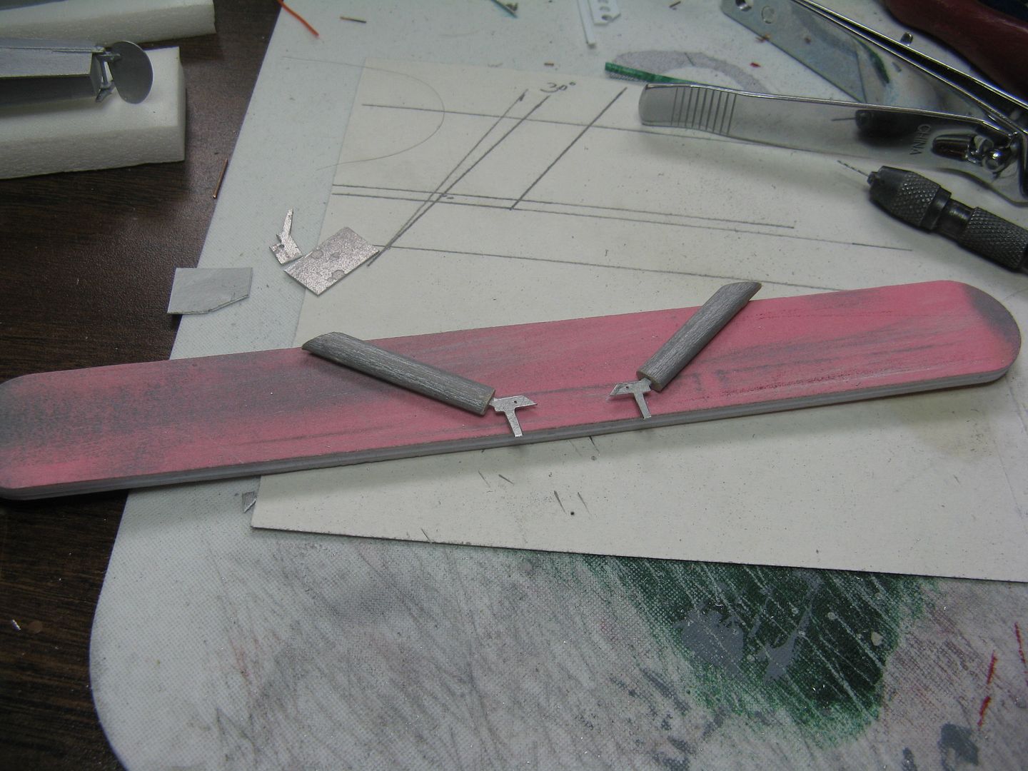
Dry fit.
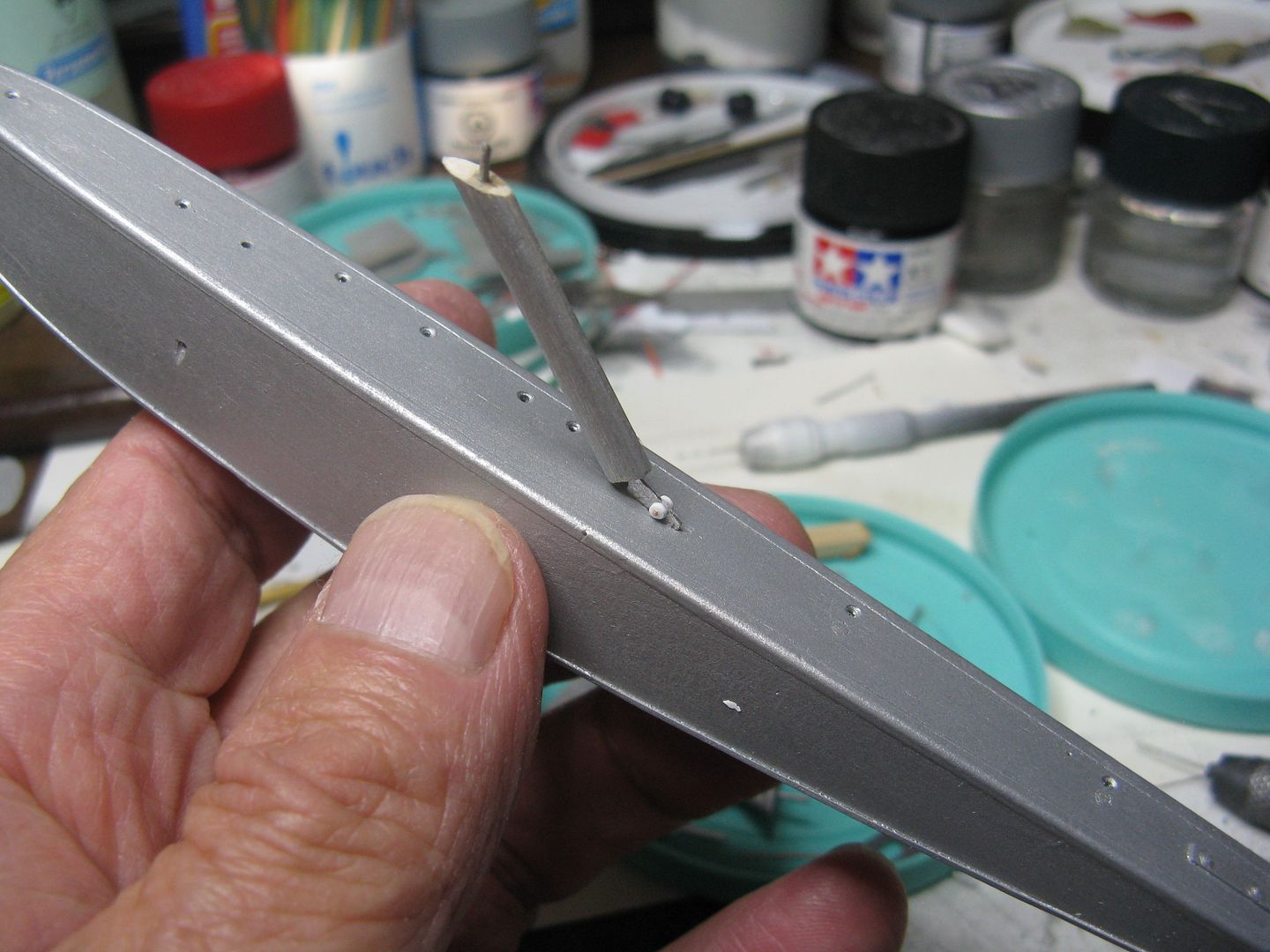
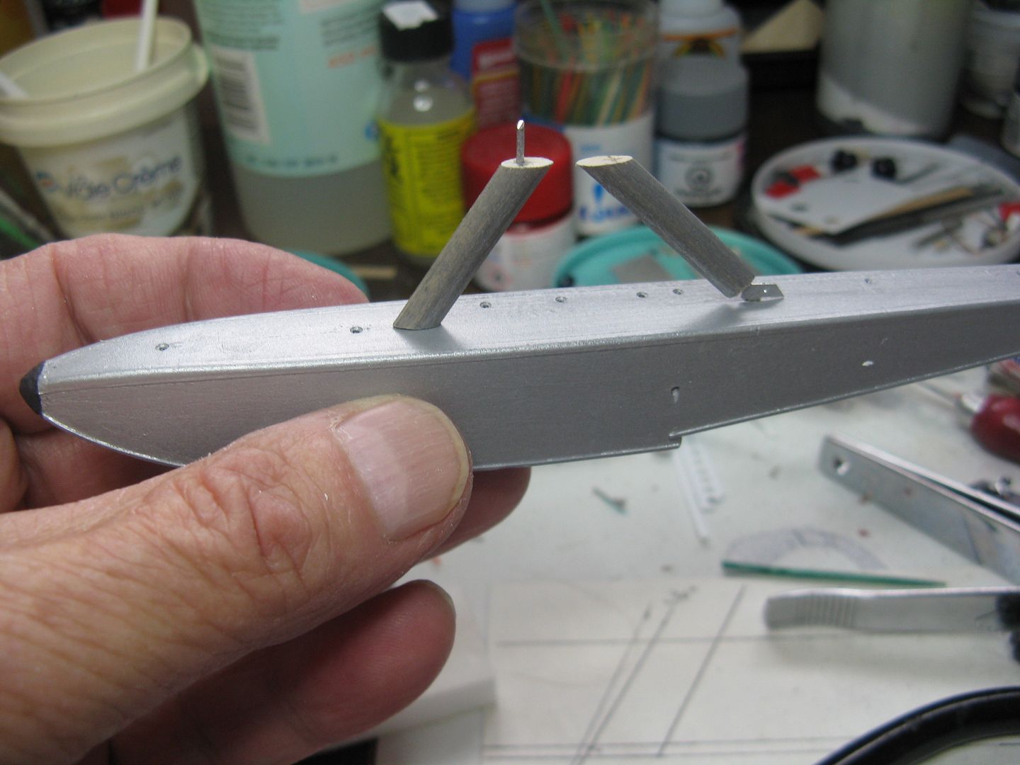
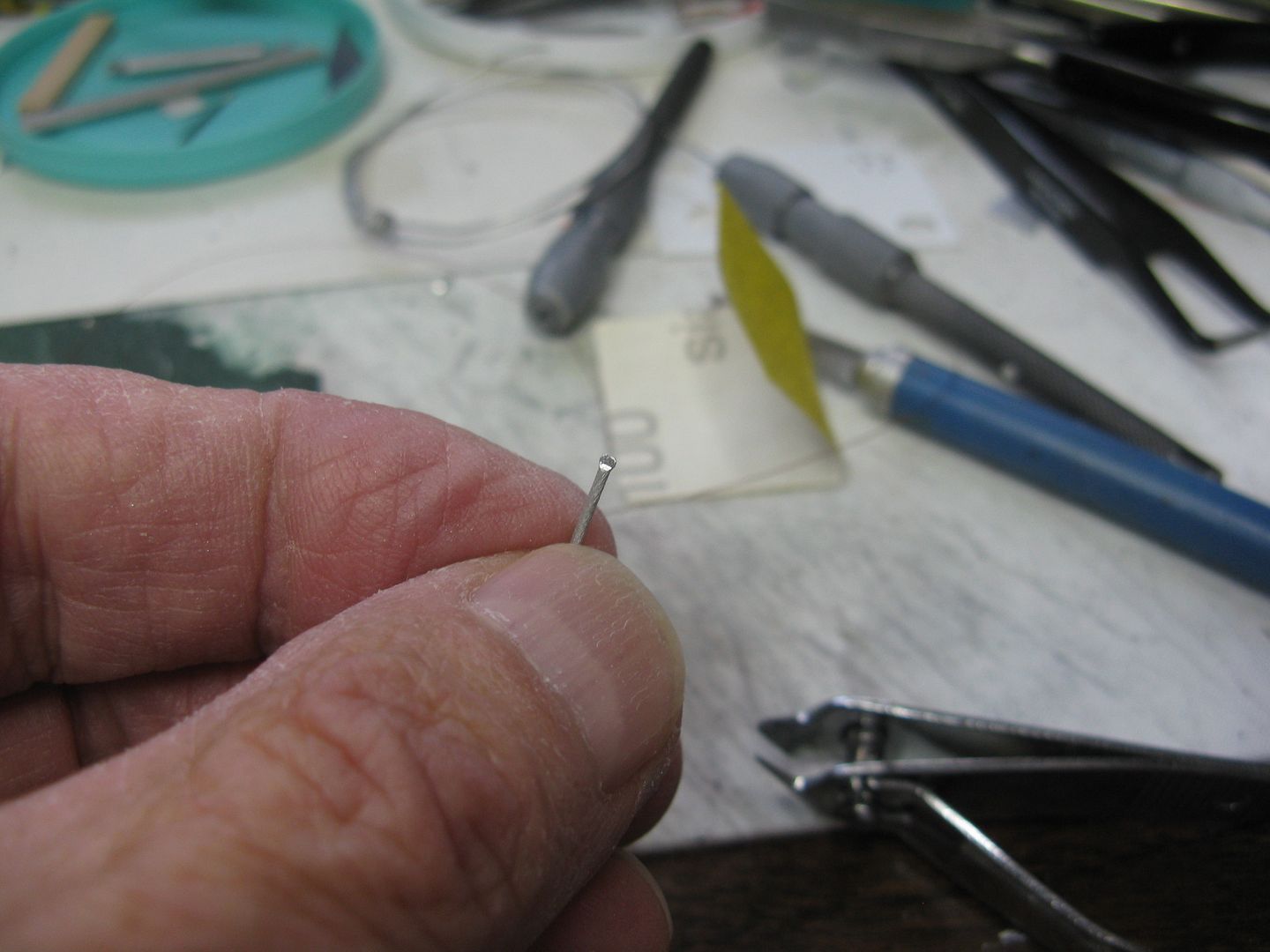
Brief digression. The Otter float - the Edo 7170 from which these are descended - has seven watertight compartments, each with its own pump out well. The Beech float - the 7850 - has an extra compartment, therefore eight pump out wells. The wells are plugged with rubber plugs each with a little thumb screw that you turn to squeezes the plug and keep the water out and to keep them in close formation with the float. They look like solid wing nuts, but a little bigger. I made 16 of those suckers, well 20 actually because some always fly off to the 4h dimension, by squeezing a short bit of 20-ga aluminum wire into a thumbscrewy shape...
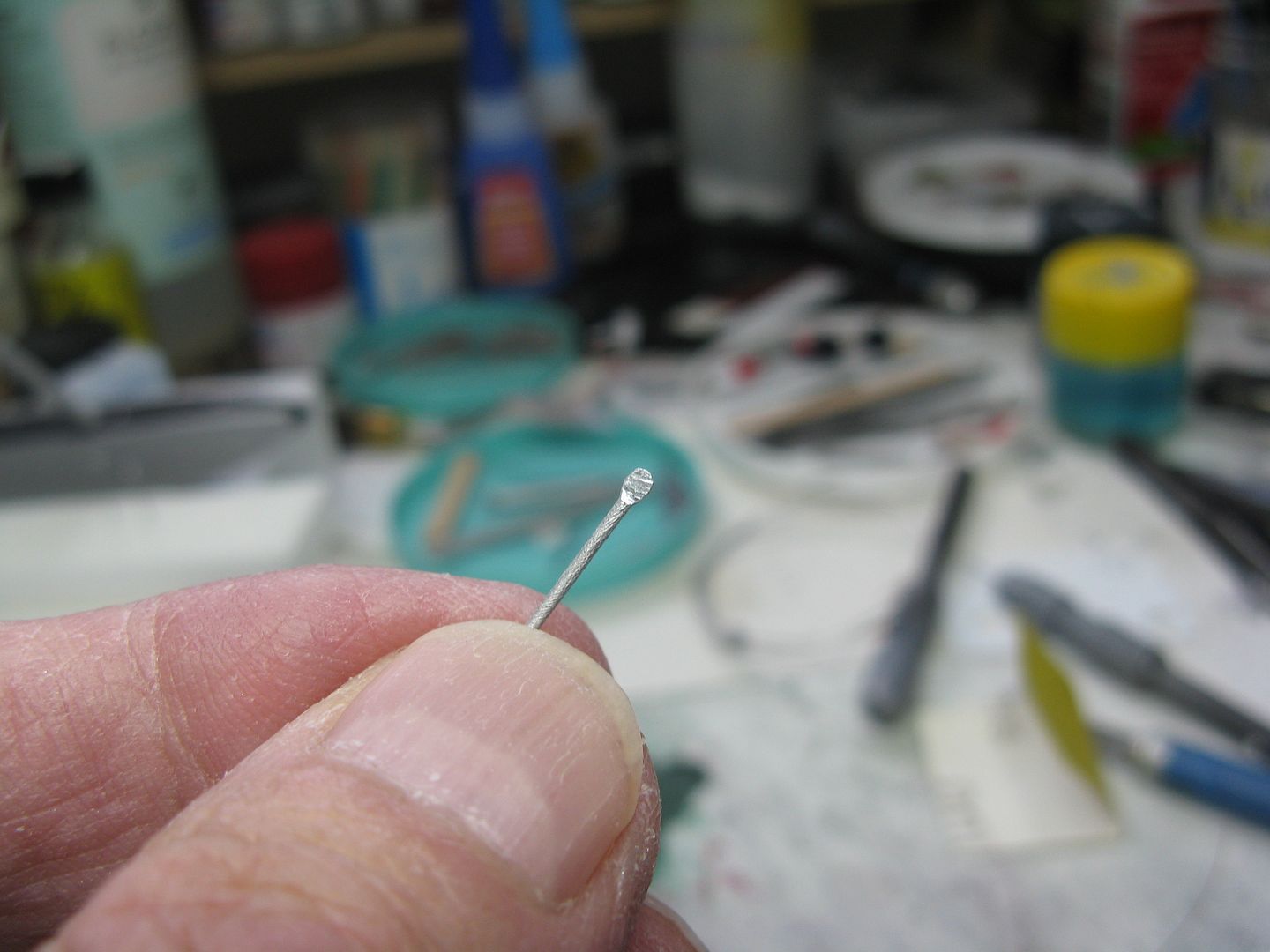
...Then rounding it out to scale, clipping off the end then inserting it into the previously drilled hole in the deck of the float that represents the pump out well.
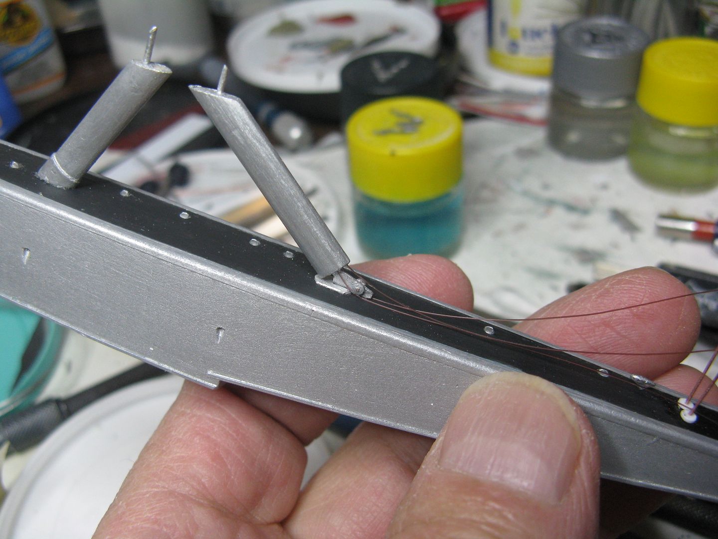
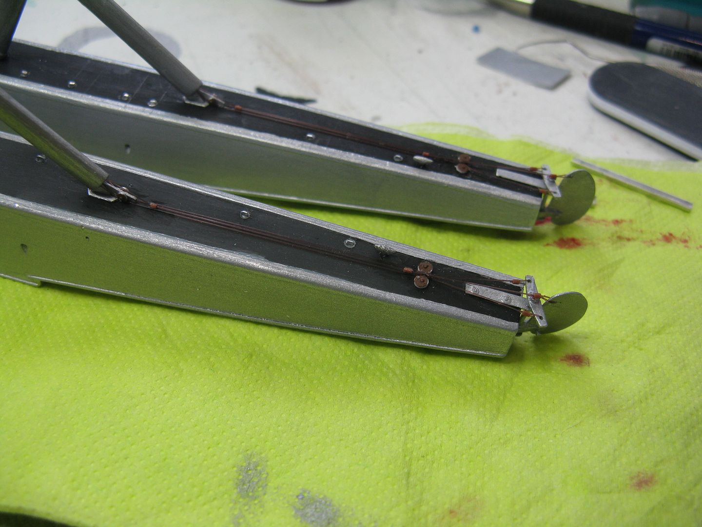
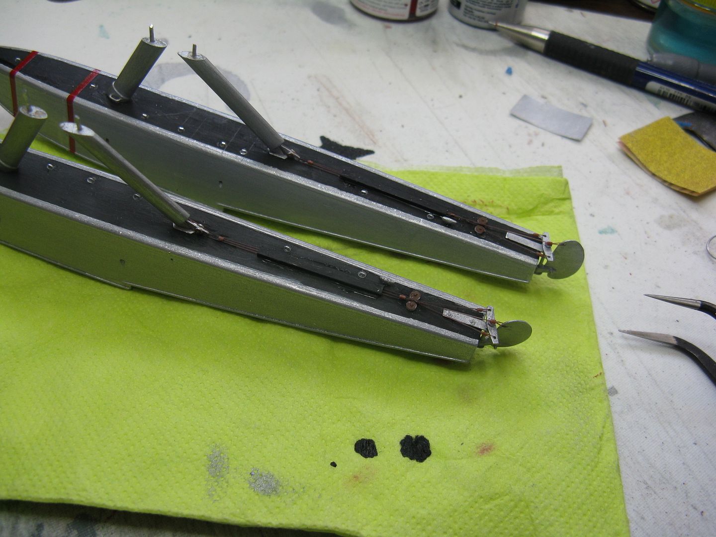
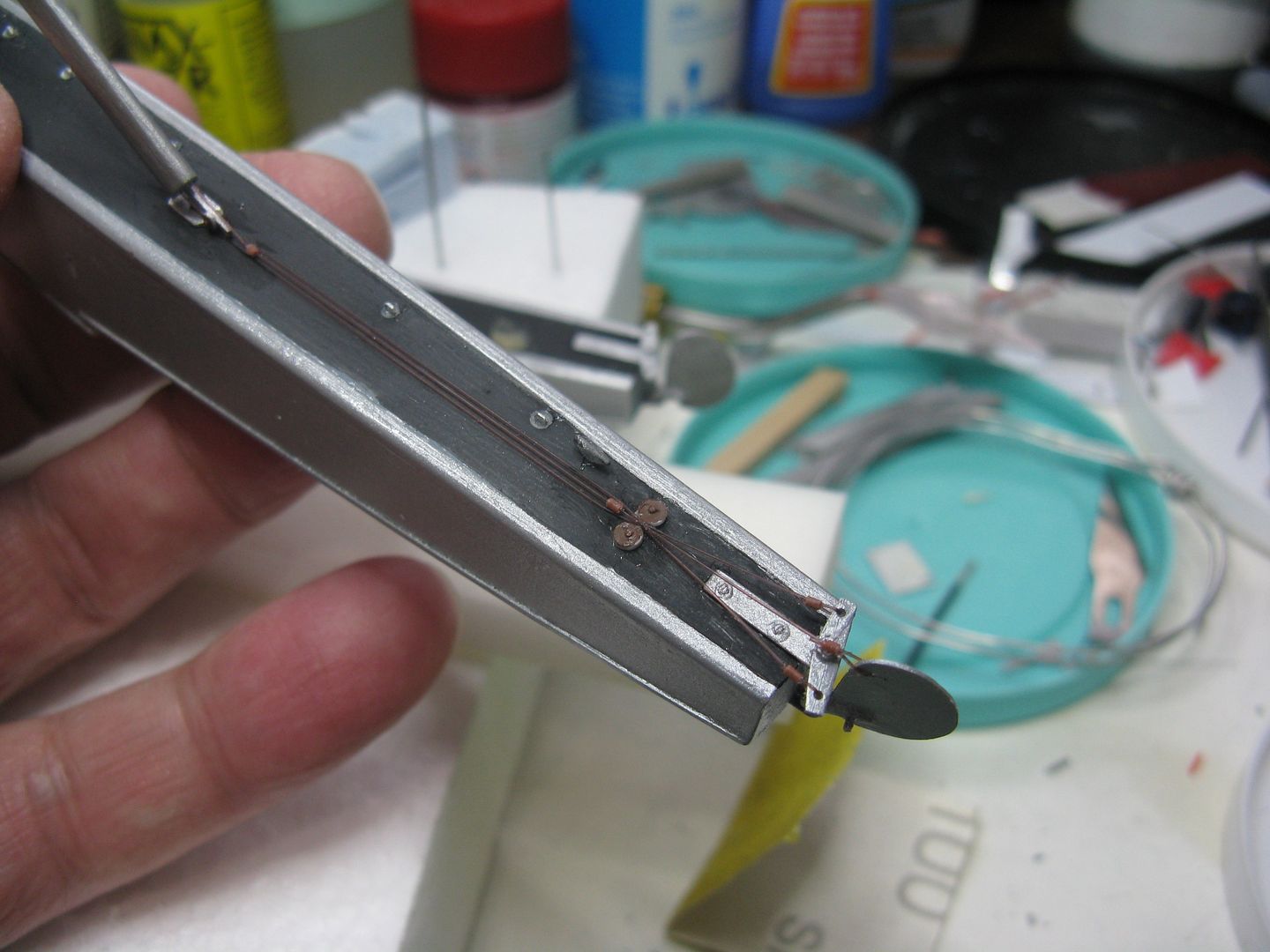
In the above photo you can see the three water rudder cables dangling out the lower end of the rear float strut. The three - from the nearest to the furthest - are the rudder connection cable the one that joins the aircraft controls, the water rudder pull-up cable the one that allows the water rudders to be retracted and extended and finally the inner one, the balance cable. The balance cable is a continuous cable from one water rudder to the other. The cables are from 4lb nylon monofilament leader line, available from Wally's sporting goods department, for a modest sum. I drilled three holes in the end of the strut with a #78 drill and shoved the end of the cable in place along with a dollop of Gorilla Glue. To make things copacetic, I ran the rudder and balance cable under two rounds of scrap styrene, pounded from a sheet using a Micro Mark punch, to represent the two pulleys found in that location. This is another reason for that weird-shaped little fitting, it must accommodate a pulley on either side. The pull-up cable is not so well treated, it has a fairlead I made from a short length of wire insulation.
From those two front units, the cables go to a second set of pulleys mounted on the deck of the float. Again the pulleys are from scrap sheet styrene, attached with bits of wire.
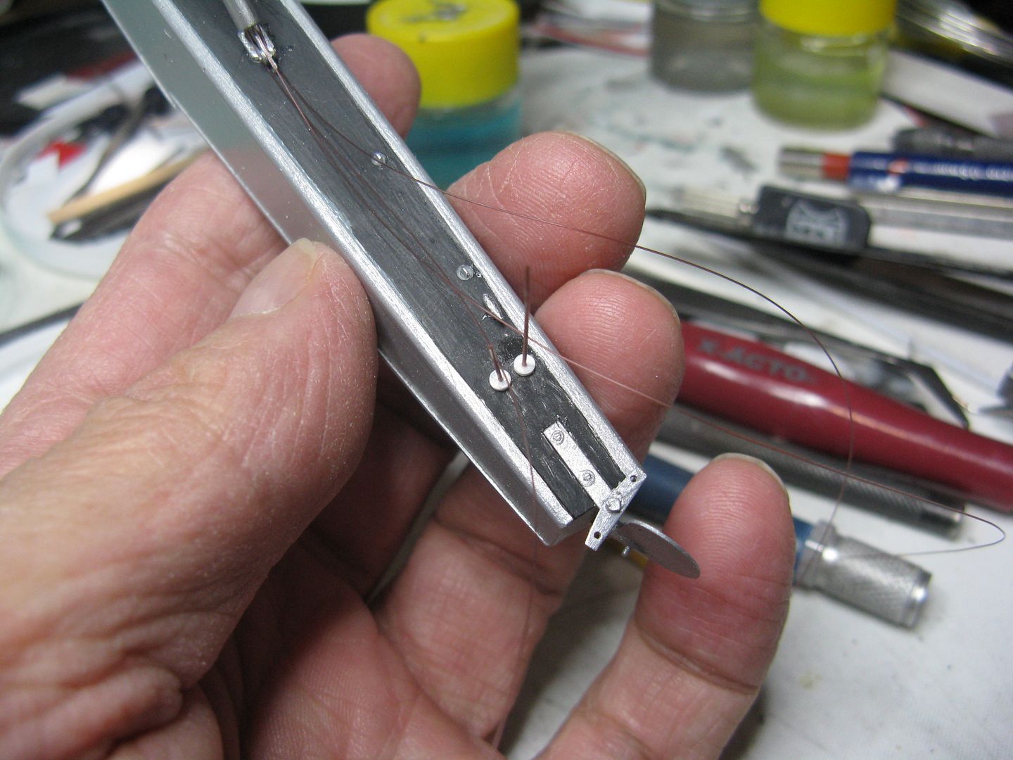
After threading through those rear pulleys, the rudder and balance cable are directed to its appropriate position on the water rudder tiller. I used a bit of modem wire insulation to represent the swaged fitting that closes the loop through the tiller. The pull-up cable goes through another fairlead, then routes through another bit of insulation on top of the water rudder post, where it passes through the hole in the top of the water rudder and is then glued in position.
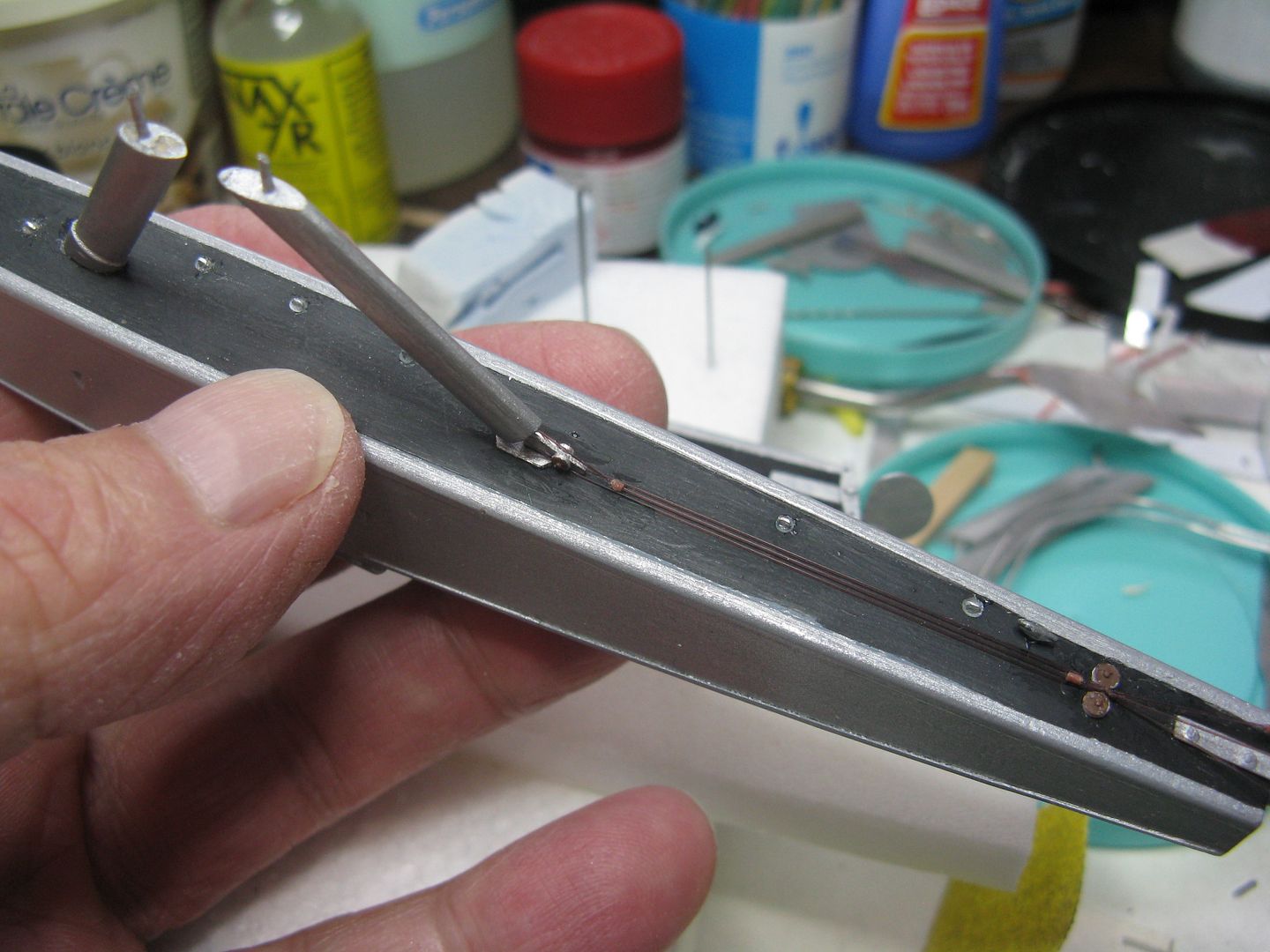
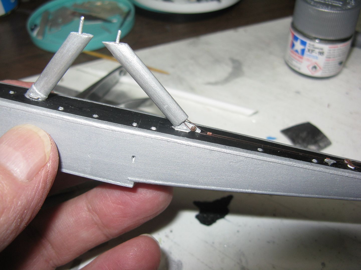
I was concerned that the rear attach fitting I had so cleverly manufactured might be a little flimsy. It's only .020 metal after all, so I came up with an idea to add a doubler on either side of the fitting where it joins the deck. If you look closely, you can see a tiny triangular piece of metal that has been added to the joint, below the strut immediately ahead of the pulley. The result was great, the joint has been stiffened 100%.
Back later to finish off the floats.
I have the floats and the main struts finished. The main struts are hefty affairs - as they must be - the airplane weighs what.. 9000 lbs? and the floats take a beating in rough water. I had no idea of the length, so I made the front one 42 scale inches, and with a 30-degree aft rake it gives around 38 inches of clear space between the deck of the float and the nacelle, at the lowest point. The front strut and the upper end of the rear strut are attached with a simple wire pin, but lower end of the rear one is more complicated. To begin with, the water rudder cables run up inside the strut to the nacelle, where by some PFM process they connect with the air rudder cables. This attachment called for some creative thinking. First, cut two funny shaped little fittings from scrap metal...

Then drill a hole in the lower end of the strut and shove the long arm of the fitting into the hole and epoxy the thing in place.

Dry fit.


Brief digression. The Otter float - the Edo 7170 from which these are descended - has seven watertight compartments, each with its own pump out well. The Beech float - the 7850 - has an extra compartment, therefore eight pump out wells. The wells are plugged with rubber plugs each with a little thumb screw that you turn to squeezes the plug and keep the water out and to keep them in close formation with the float. They look like solid wing nuts, but a little bigger. I made 16 of those suckers, well 20 actually because some always fly off to the 4h dimension, by squeezing a short bit of 20-ga aluminum wire into a thumbscrewy shape...

...Then rounding it out to scale, clipping off the end then inserting it into the previously drilled hole in the deck of the float that represents the pump out well.


In the above photo you can see the three water rudder cables dangling out the lower end of the rear float strut. The three - from the nearest to the furthest - are the rudder connection cable the one that joins the aircraft controls, the water rudder pull-up cable the one that allows the water rudders to be retracted and extended and finally the inner one, the balance cable. The balance cable is a continuous cable from one water rudder to the other. The cables are from 4lb nylon monofilament leader line, available from Wally's sporting goods department, for a modest sum. I drilled three holes in the end of the strut with a #78 drill and shoved the end of the cable in place along with a dollop of Gorilla Glue. To make things copacetic, I ran the rudder and balance cable under two rounds of scrap styrene, pounded from a sheet using a Micro Mark punch, to represent the two pulleys found in that location. This is another reason for that weird-shaped little fitting, it must accommodate a pulley on either side. The pull-up cable is not so well treated, it has a fairlead I made from a short length of wire insulation.
From those two front units, the cables go to a second set of pulleys mounted on the deck of the float. Again the pulleys are from scrap sheet styrene, attached with bits of wire.

After threading through those rear pulleys, the rudder and balance cable are directed to its appropriate position on the water rudder tiller. I used a bit of modem wire insulation to represent the swaged fitting that closes the loop through the tiller. The pull-up cable goes through another fairlead, then routes through another bit of insulation on top of the water rudder post, where it passes through the hole in the top of the water rudder and is then glued in position.


I was concerned that the rear attach fitting I had so cleverly manufactured might be a little flimsy. It's only .020 metal after all, so I came up with an idea to add a doubler on either side of the fitting where it joins the deck. If you look closely, you can see a tiny triangular piece of metal that has been added to the joint, below the strut immediately ahead of the pulley. The result was great, the joint has been stiffened 100%.

Back later to finish off the floats.

