Adam Baker
Active member
This is a kit I received in December, and once built, the pictures I take, will be used as box art by the manufacturer.
I made some decent progress before the end of the year, and then like the rest of my modeling, just feel on its face. I had lost any and all desire & motivation to do any modeling, but in the last week or so I've been getting back into it, spending several hours at my bench (probably helped that my internet was out for 3 days).
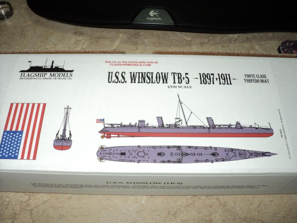
So anyway. The kit is the USS Winslow, a torpedo boat commissioned in 1897, and used during the Spanish American War. It was decommissioned in 1910, and sold for scrap in 1920.
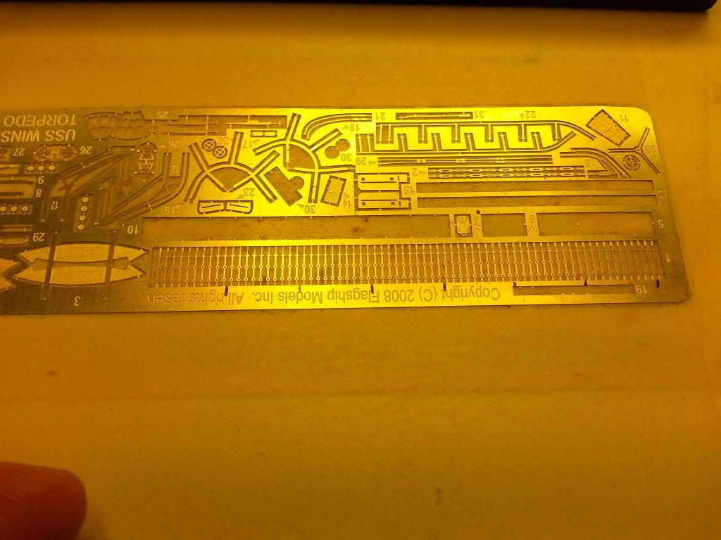
Kit is predominately resin, w/ a pretty decent photoetch fret, and 2 pieces of brass rod. Kit manufacturer is Flagship Models, which produces mostly Civil War era Ironclads & other ships of that time frame.
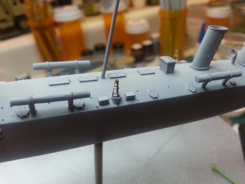
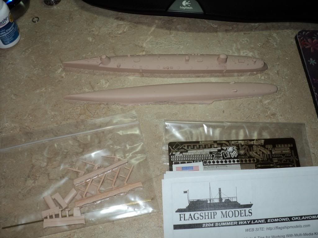
And here's the layout of parts. Kit comes with a 2 piece hull allowing for waterline if the builder so wishes. I chose to go w/ the full hull. In the plastic baggy in the lower left are the 2 exhaust funnels, 4 torpedo storage containers, 3 torpedo launchers, 8 air vents (my kit only came w/ 6, waiting on 2 more to arrive), 2 propellers, and the propeller shaft supports. Also included are 2 brass rods, one for the propeller shafts, and one for the mast. On the right is the photoetch fret.
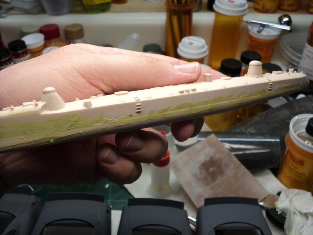
Ok, enough gratuitous advertising, haha. When it came to the actual construction, I had some trouble getting the 2 halves together, the bottom half had a pretty bad wedge shape to it, that I had a lot of trouble correcting, so once I was able to at least get a partial flat surface sanded onto it, I glued the 2 halves together as best as I could. This resulted in a pretty large gap almost all the way around, so I filled it w/ strips of styrene until the gap was filled. I then sanded it smooth. I also had to deal w/ a pretty massive air bubble that was present in each hull half, and actually the bubbles aligned w/ each other almost perfectly, creating a huge hole in the side of the hull, which I filled w/ Milliput, and let sit for several days to get good & dry.
Here's where the hole was, after being filled w/ Milliput
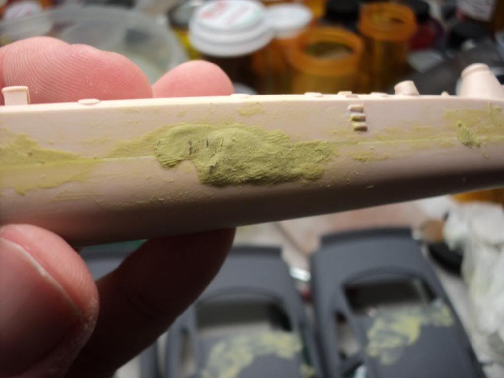
And here you can see where I had applied Milliput over the styrene strips.
I got it all cleaned up and hit the whole thing w/ sandable while primer, and that's where it sat for several weeks.
A couple weeks ago I finally got back on it, I filled a few problem areas w/ Bondo Glazing putty, and then got that cleaned up.
I then moved on to the photoetch & the separate resin pieces, which is where I'm at now.
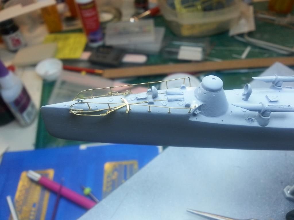
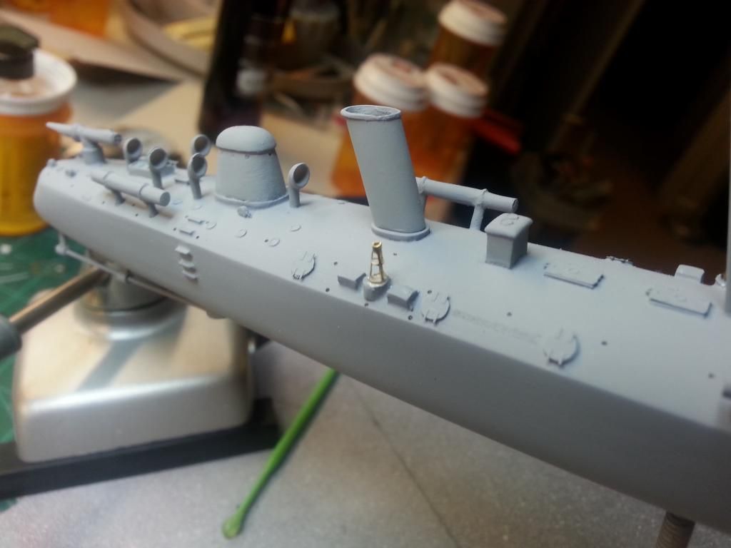
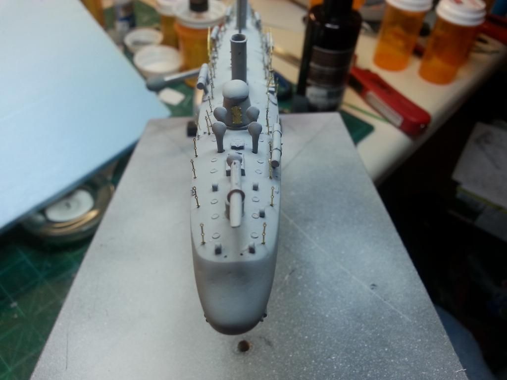
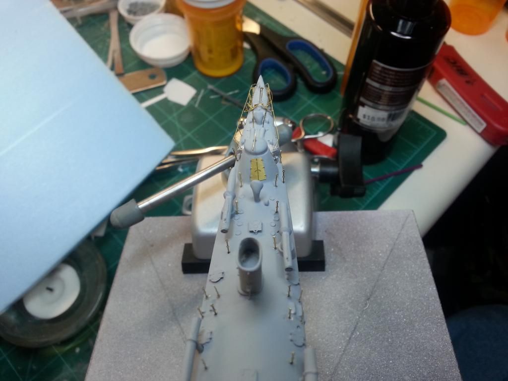
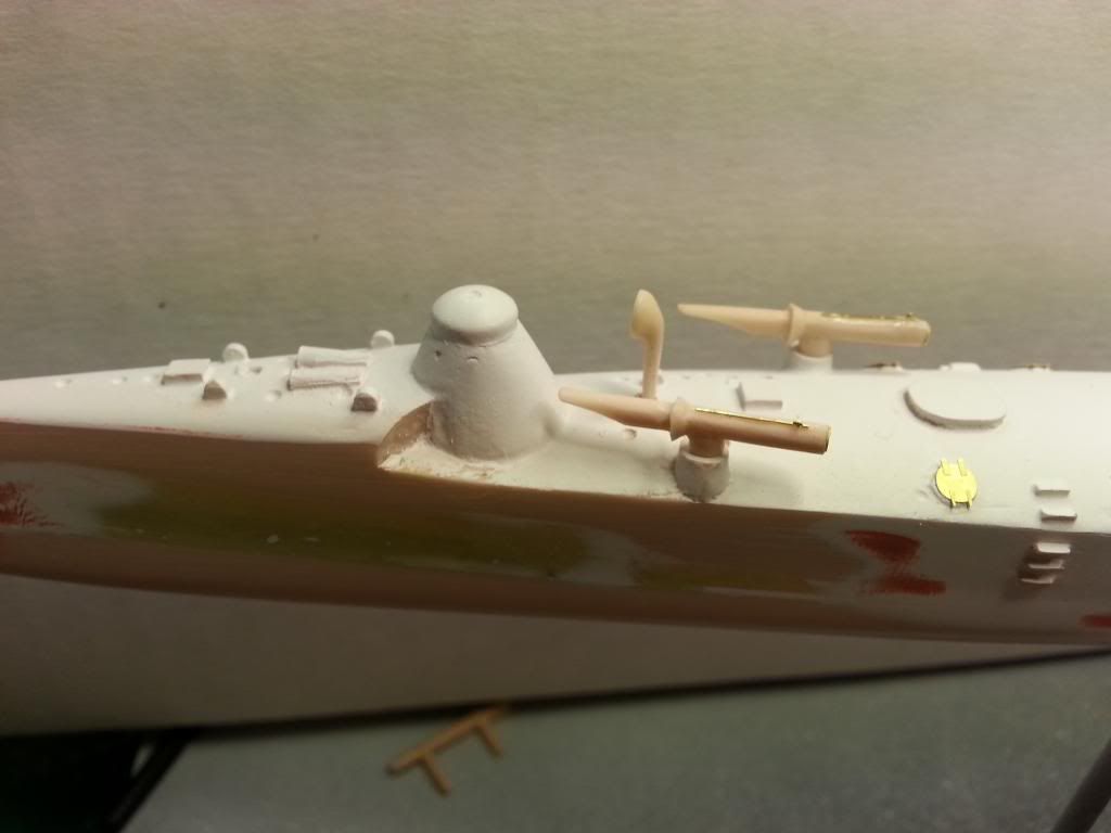
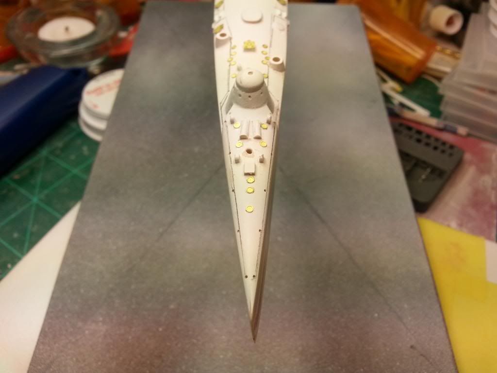
I started w/ the torpedo launchers. All 3 required some pretty decent work to get cleaned up, but nothing too major. To place the launchers on the ship, I drilled locating holes in their pedestals on the hull, and then worked on assembling them. Each launcher has 2 pieces of photoetch, a wheel type thing at the rear, and what looks like an aiming device on the top.
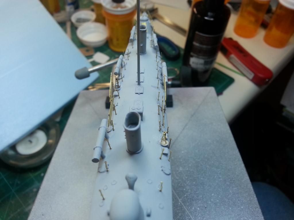
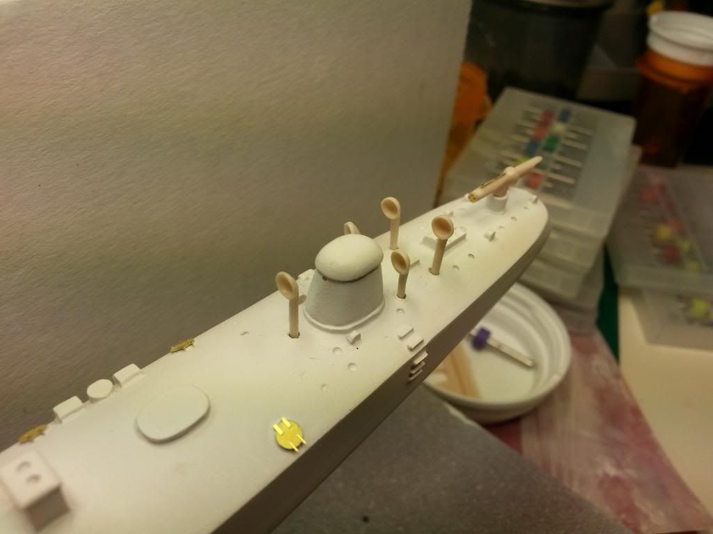
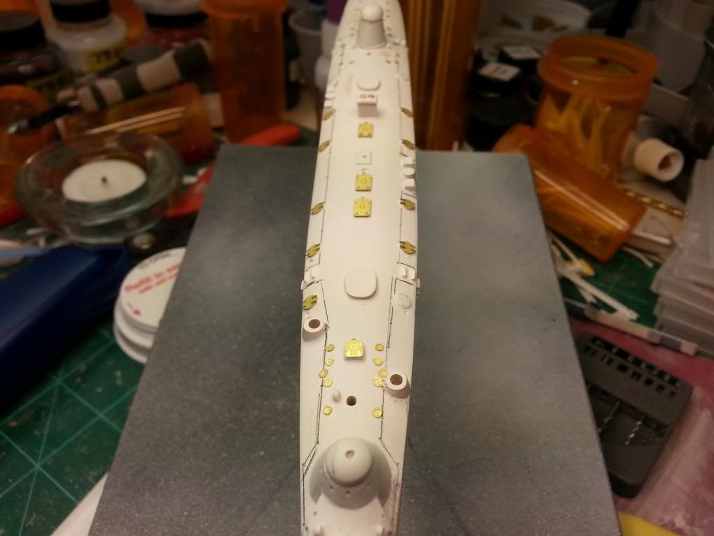
Once that was done, I started working on cleaning up the vent tubes, and prepping the hull for those. The instructions state that the vents are taller than required, so they have to be trimmed to length. TO help locate them, and help to prevent issues w/ them breaking off, I drilled holes in the hull to hold the vents. They still need to be trimmed to the correct height. There should be 8 vents, 6 at the stern and 2 at the bow.
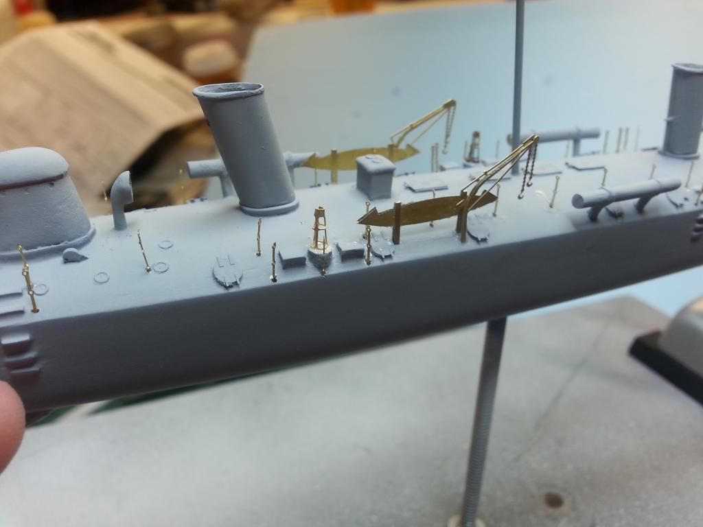
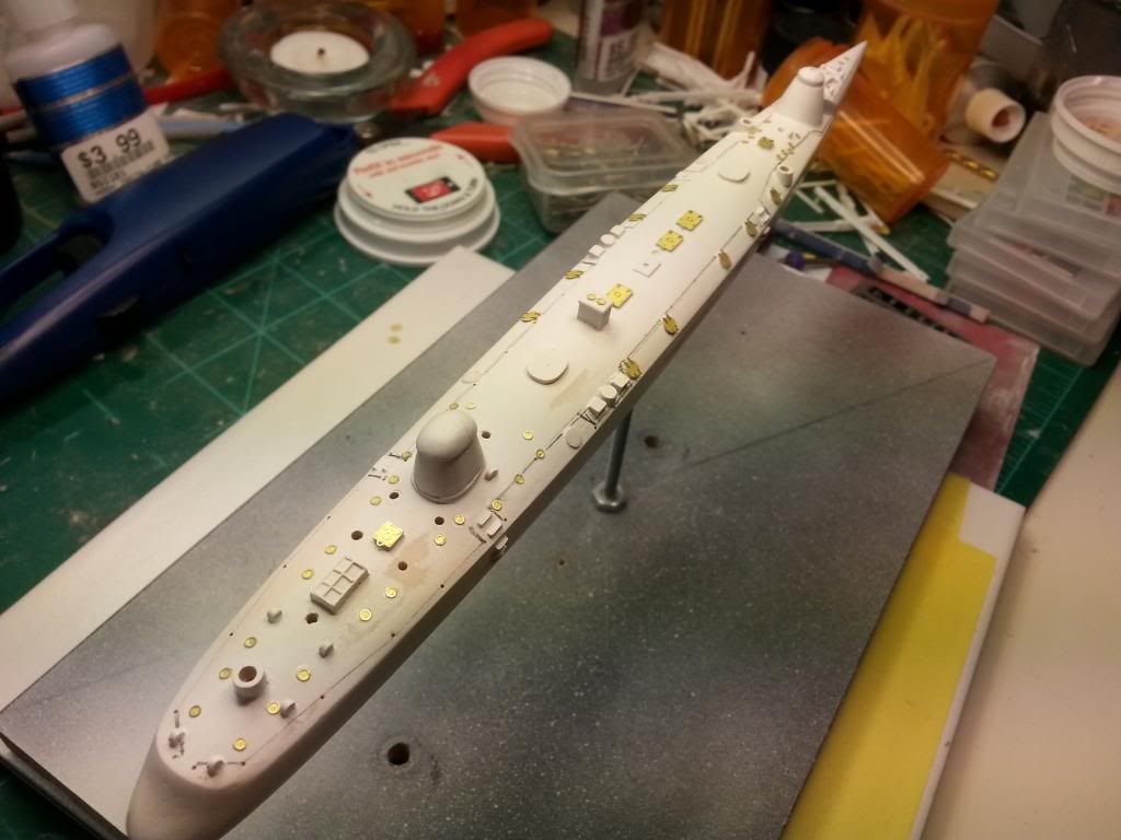
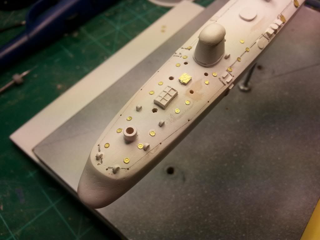
Next was the beginning of the PE on the hull itself. I applied the 12 hatches, 6 down each side, and then applied the 40+ port holes. Thankfully the port holes have little depressions in the hull to locate them, but in a few places there are extra depressions where there shouldn't be a port hole, and in other places, there's no depression at all where there should be a port hole. For places that lacked the depression, I used a pin vise to make them. Wasn't sure what the best method for attaching the port holes was, so I just filled each depression w/ a drop of superglue and then dropped the PE in place over the glue, which seemed to work pretty good.
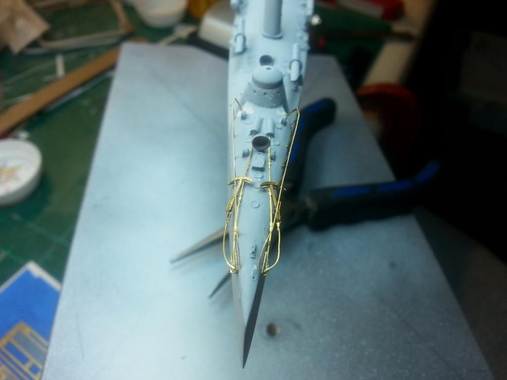
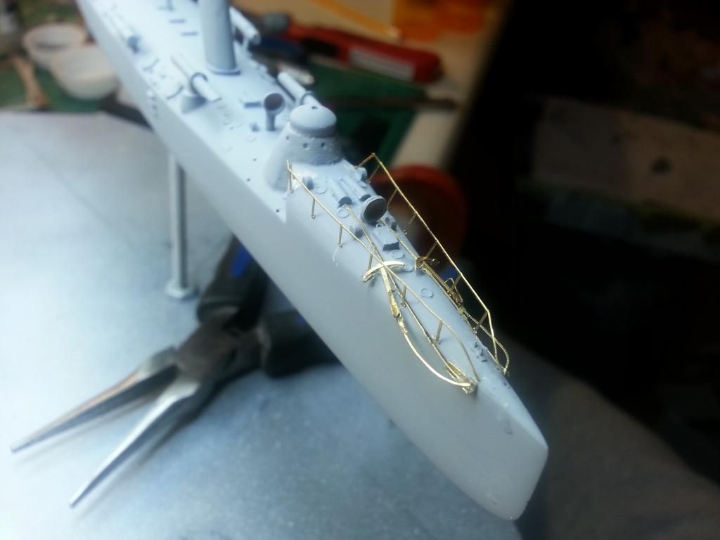
It was at this point that I decided it was time to start thinking about the railing stanchions. The PE fret comes w/ 71 individual railing stanchions. On the instruction sheet is a layout of how the railings are supposed to be placed, and then its left up to the builder to figure out how to get them in place. Along w/ the layout, the sheet also notes that the stanchions are approximately 6' apart, which works out to 3/8" in scale. I decided the best method to get it all laid out was to use a pencil & a straight edge, so I could make sure my railings didn't wander all over the deck, since any railings that aren't in line will probably be pretty noticeable. The stanchions have small pins at the bottom for locating, so I measured the size, and then used a slightly larger drill bit to drill out all the holes.
And here you can see the stanchions on the fret. Sorry for the less than great pic, brass PE backed by yellow tape doesn't work real great in pictures. To give an idea of size, the stanchions are only .2" (~5mm) tall and are .015" (~.4mm) wide. I used a .020 (.5mm) drill bit for the locating holes, all 64 of them. And then the stanchions have holes in them, for threading the rail. Don't have any idea at this point what I'll be using for the railings. Thinking I might see if I can get some sprue to stretch that thin.
I made some decent progress before the end of the year, and then like the rest of my modeling, just feel on its face. I had lost any and all desire & motivation to do any modeling, but in the last week or so I've been getting back into it, spending several hours at my bench (probably helped that my internet was out for 3 days).
So anyway. The kit is the USS Winslow, a torpedo boat commissioned in 1897, and used during the Spanish American War. It was decommissioned in 1910, and sold for scrap in 1920.
Kit is predominately resin, w/ a pretty decent photoetch fret, and 2 pieces of brass rod. Kit manufacturer is Flagship Models, which produces mostly Civil War era Ironclads & other ships of that time frame.
And here's the layout of parts. Kit comes with a 2 piece hull allowing for waterline if the builder so wishes. I chose to go w/ the full hull. In the plastic baggy in the lower left are the 2 exhaust funnels, 4 torpedo storage containers, 3 torpedo launchers, 8 air vents (my kit only came w/ 6, waiting on 2 more to arrive), 2 propellers, and the propeller shaft supports. Also included are 2 brass rods, one for the propeller shafts, and one for the mast. On the right is the photoetch fret.
Ok, enough gratuitous advertising, haha. When it came to the actual construction, I had some trouble getting the 2 halves together, the bottom half had a pretty bad wedge shape to it, that I had a lot of trouble correcting, so once I was able to at least get a partial flat surface sanded onto it, I glued the 2 halves together as best as I could. This resulted in a pretty large gap almost all the way around, so I filled it w/ strips of styrene until the gap was filled. I then sanded it smooth. I also had to deal w/ a pretty massive air bubble that was present in each hull half, and actually the bubbles aligned w/ each other almost perfectly, creating a huge hole in the side of the hull, which I filled w/ Milliput, and let sit for several days to get good & dry.
Here's where the hole was, after being filled w/ Milliput
And here you can see where I had applied Milliput over the styrene strips.
I got it all cleaned up and hit the whole thing w/ sandable while primer, and that's where it sat for several weeks.
A couple weeks ago I finally got back on it, I filled a few problem areas w/ Bondo Glazing putty, and then got that cleaned up.
I then moved on to the photoetch & the separate resin pieces, which is where I'm at now.
I started w/ the torpedo launchers. All 3 required some pretty decent work to get cleaned up, but nothing too major. To place the launchers on the ship, I drilled locating holes in their pedestals on the hull, and then worked on assembling them. Each launcher has 2 pieces of photoetch, a wheel type thing at the rear, and what looks like an aiming device on the top.
Once that was done, I started working on cleaning up the vent tubes, and prepping the hull for those. The instructions state that the vents are taller than required, so they have to be trimmed to length. TO help locate them, and help to prevent issues w/ them breaking off, I drilled holes in the hull to hold the vents. They still need to be trimmed to the correct height. There should be 8 vents, 6 at the stern and 2 at the bow.
Next was the beginning of the PE on the hull itself. I applied the 12 hatches, 6 down each side, and then applied the 40+ port holes. Thankfully the port holes have little depressions in the hull to locate them, but in a few places there are extra depressions where there shouldn't be a port hole, and in other places, there's no depression at all where there should be a port hole. For places that lacked the depression, I used a pin vise to make them. Wasn't sure what the best method for attaching the port holes was, so I just filled each depression w/ a drop of superglue and then dropped the PE in place over the glue, which seemed to work pretty good.
It was at this point that I decided it was time to start thinking about the railing stanchions. The PE fret comes w/ 71 individual railing stanchions. On the instruction sheet is a layout of how the railings are supposed to be placed, and then its left up to the builder to figure out how to get them in place. Along w/ the layout, the sheet also notes that the stanchions are approximately 6' apart, which works out to 3/8" in scale. I decided the best method to get it all laid out was to use a pencil & a straight edge, so I could make sure my railings didn't wander all over the deck, since any railings that aren't in line will probably be pretty noticeable. The stanchions have small pins at the bottom for locating, so I measured the size, and then used a slightly larger drill bit to drill out all the holes.
And here you can see the stanchions on the fret. Sorry for the less than great pic, brass PE backed by yellow tape doesn't work real great in pictures. To give an idea of size, the stanchions are only .2" (~5mm) tall and are .015" (~.4mm) wide. I used a .020 (.5mm) drill bit for the locating holes, all 64 of them. And then the stanchions have holes in them, for threading the rail. Don't have any idea at this point what I'll be using for the railings. Thinking I might see if I can get some sprue to stretch that thin.

")