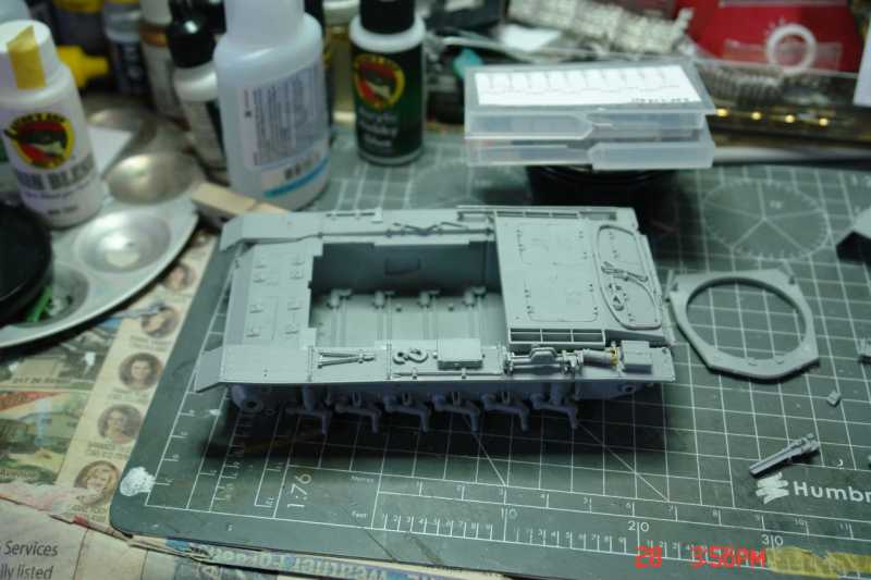
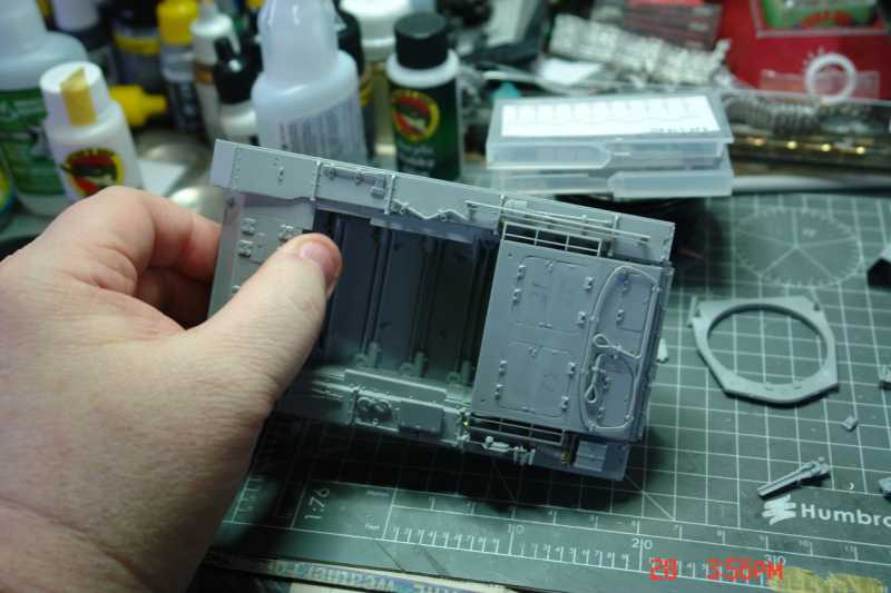
Okay, I'm not all that fast at modeling anymore so have not gotten a lot done yet today. Hull is started.
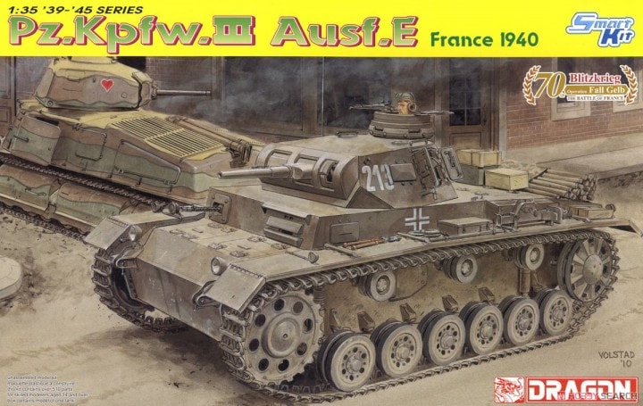
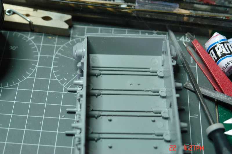
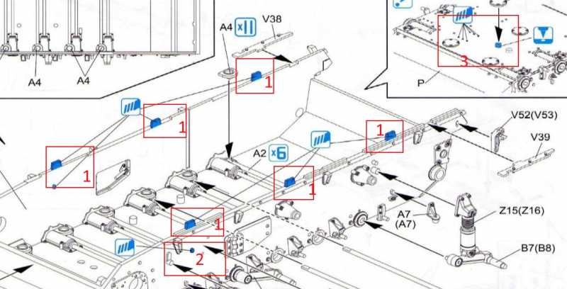
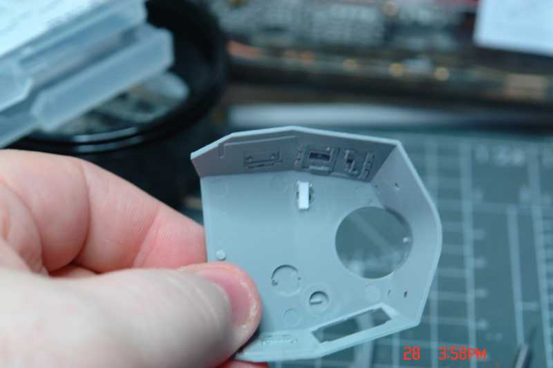
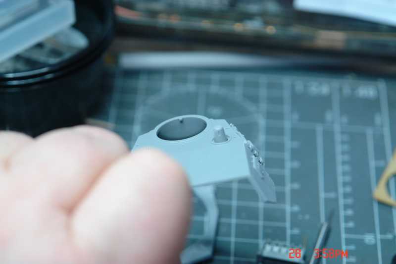
Now a bit of explanation in case it helps someone who has never done a Pz III or Stug III by Dragon. The instructions are jam packed and can be very busy. Because they reuse a lot of sprues. The sprues are colour coded. So A comes in blue and black, not the sprue the instructions. I got caught on my first build. Another thing that caught me the first time because I was not paying attention are some slab sided sprue gates on the top of the hull. Number
1 here.
They have to be removed. I didnt do it the first time and it took a bit to figure out why the kit would not go together, true story :laugh:
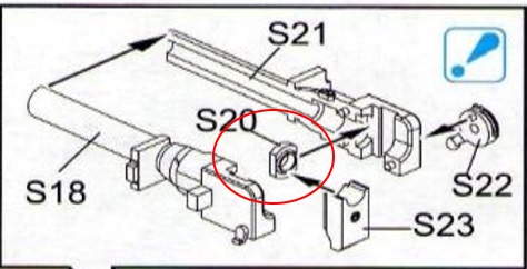
Specific to this build you need to drill a hole. in the hull bottom
3 for another access panel. and a bolt head
2 has to be removed from both sides of the hull.
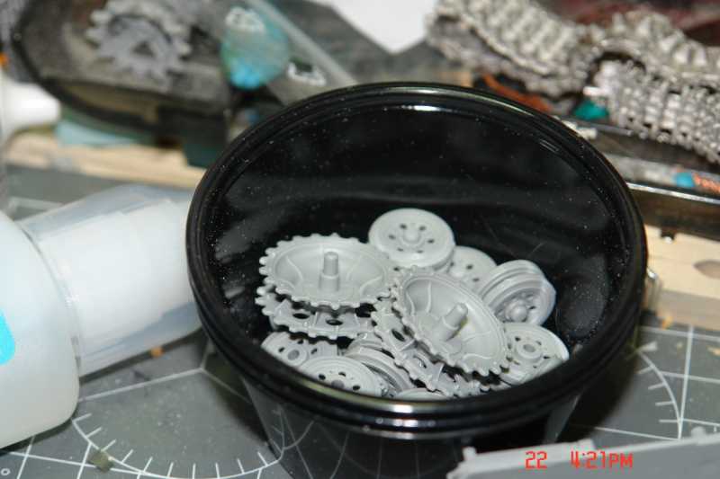
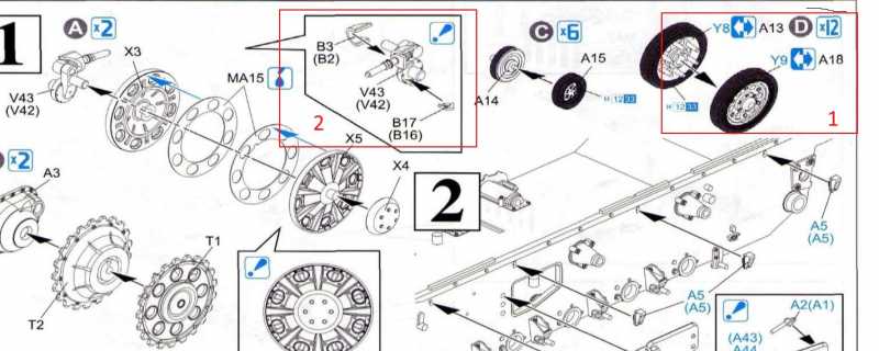
Dragon gives an option of 2 types of wheels but does not give any guidance. It took a bit of research to choose the correct wheel.
Originally the PzKpfw III Ausf. E had narrow 75mm wide road wheels. After the French campaign towards the end of 1940 the wheels were changed to wider 95mm wide wheels. Those where retrofitted and were for the wider track. You can find pictures every now and again with both road wheels present. As I am doing a vehicle used in the invasion of France (that could change to Poland) I needed to use the narrow wheels
1 from fret Y. I marked the rear track tensioner and idler assembly
2 as I find it much easier to add this to the hull without the wheel and add the wheel much later. I also attach the gear housings on the forward hull at this time leaving the drive sprockets again till much later.
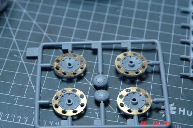
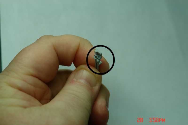
For the return idler I cut out the PE and left the wheels attached to the sprue. I stacked all the pe together and used a moto tool with a diamond bur to clean the pe gates inside. Then painted the wheels with gator glue and put the pe in. Looks like 1 is slightly bent and sticking up. When its all dry I'll clamp it down and give it some thin crazy glue. By leaving the wheels on the sprues it made an easy handle to do the work.
Let me know what you think. If I'm going into too much detail let me know for future posts.
James

