• Modelers Alliance has updated the forum software on our website. We have migrated all post, content and user accounts but we could not migrate the passwords.
    This requires that you manually reset your password.
    Please click here, http://modelersalliance.org/forums/login to go to logon page and use the "Forgot your Password" option.

Working With Photo Etch (PE)

TONY,

Great Job !! These Rock. All of them. Th working hinges seem a little daunting ... do they really work ?

If Voyager & Griffon are making these hinges ... th least that DML,Tamiya & AFV can do is to make tools with no molded clamps ! I know once & a while Dragon will drop th clamp-less tools into a kit along with th reg. tools.


Again ... Keep it a Rollin Great Job !!


ERIK
 
:notworthy (y) Awesome Tony. I've booked marked this for when I get the courage to tackle PE again, especially hinges :woohoo:

Rob
www.scratchmod.com
 
Thanks Tony, you must have read my mind since I just bought 2 sets of modern german tool clamps on Ebay for my SLT-56 project because unfortunately they are not included in the 600pcs Voyager set I am using.

Joe
 
You guys are most Welcome,my pleasure.:blush:

"Storage Boxes"

I make all my boxes just about the same way. Every now and then you'll run across what I call a wrap around side box but I still fold it almost the same way.

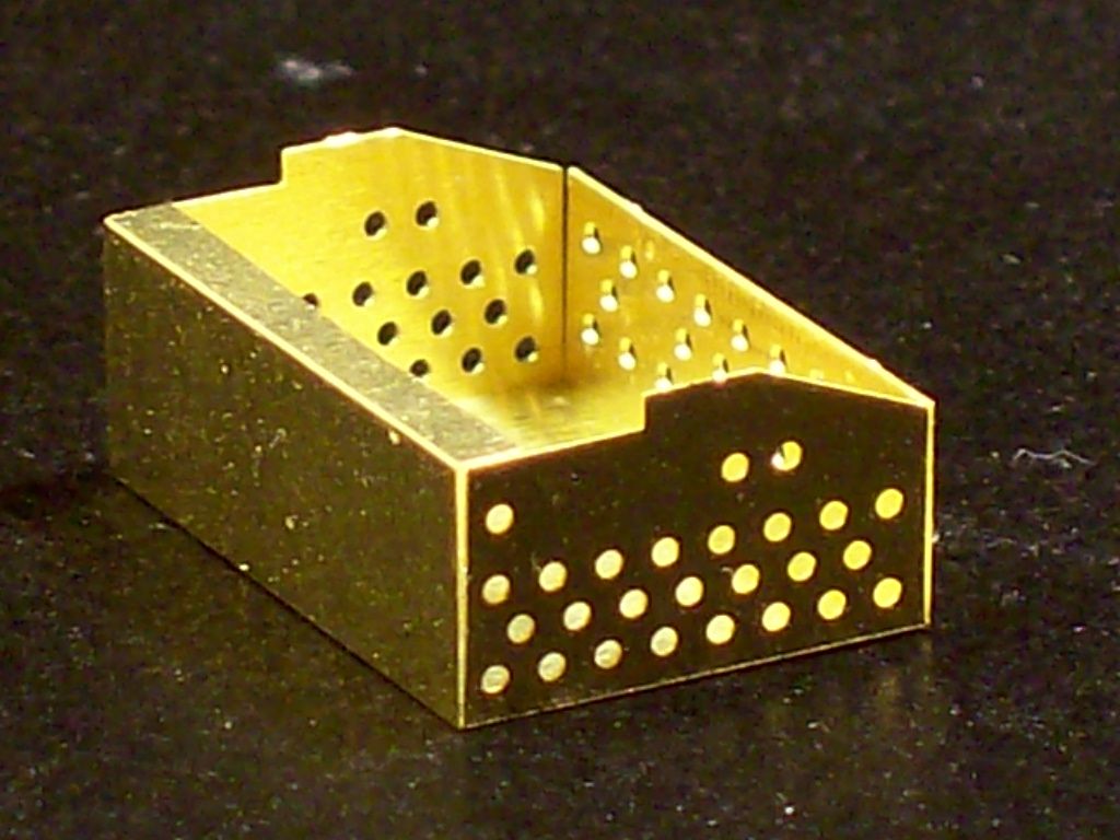
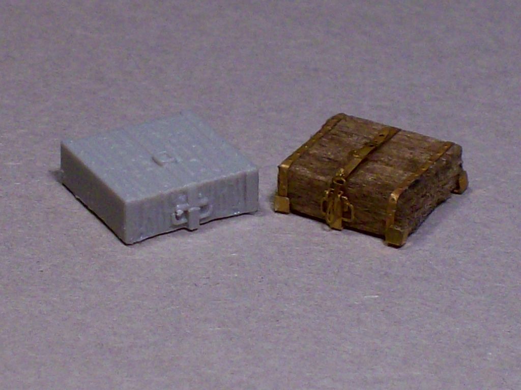
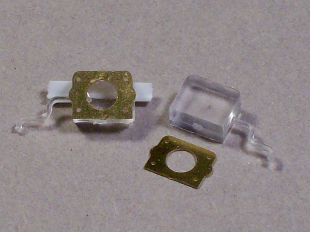
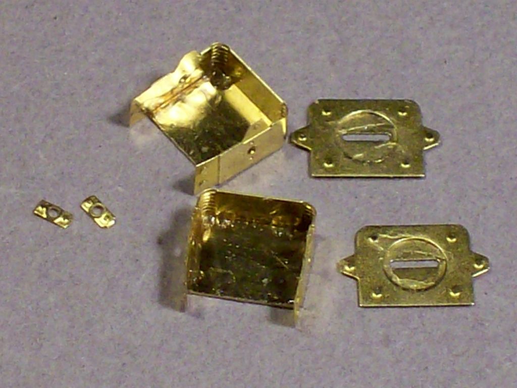
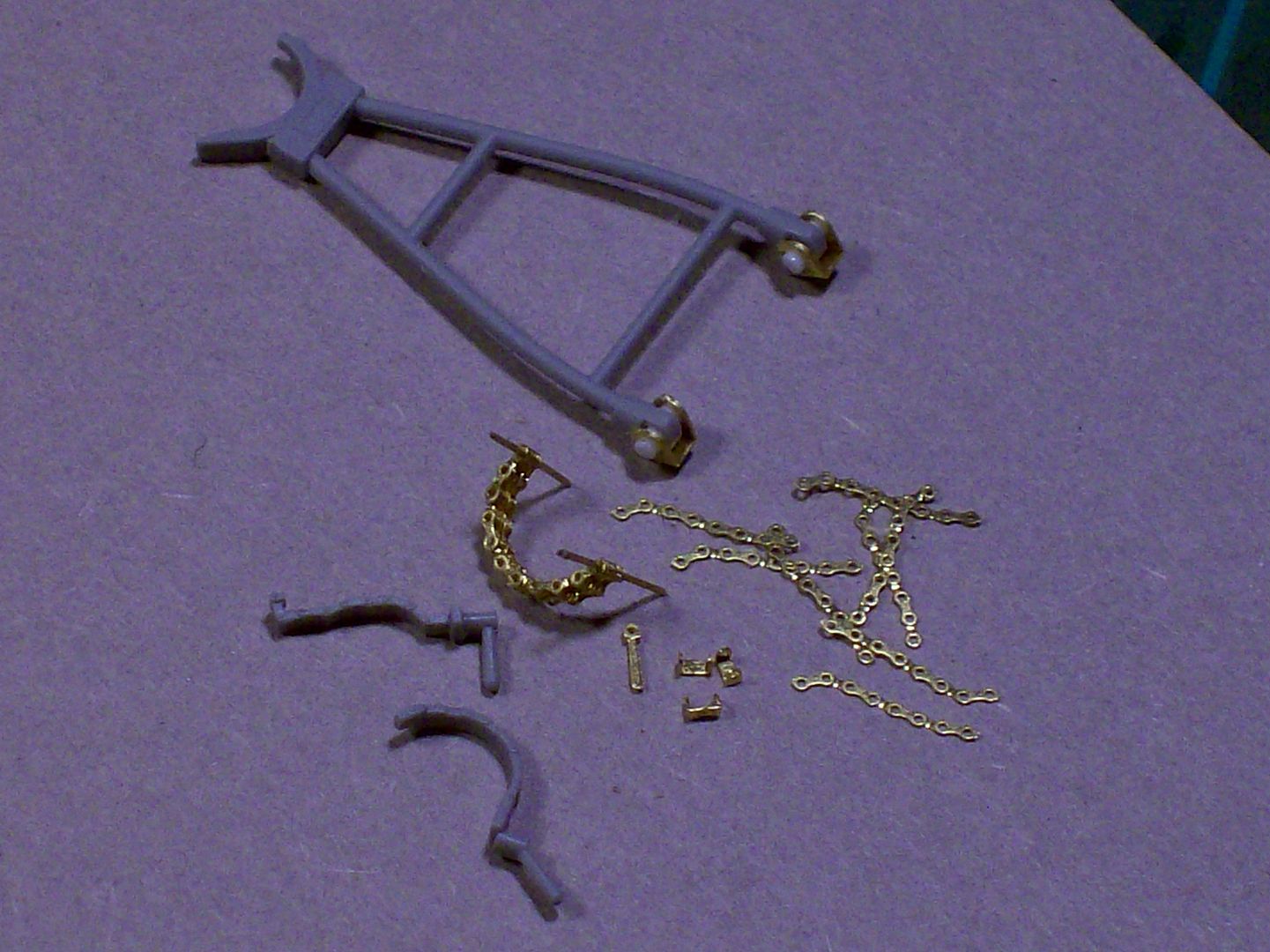
For this demo we'll use a box you see on a lot of the German 38(t)models. It's used for tools and jack storage. These parts are from a Griffon PE set and there's the main body of the box,the lib with hinge and the two latches.
100_0877.jpg


I'll start with the rear wall,using my Hold-N-Fold,where you can see the two scored lines. One marks where to fold for the base of the wall the other is for a lip that folds to the inside. I'll fold the base line first and then move it out and fold the lip.
Yeah the picture is black but you can see how close I place the edge of the folding shoe to the line. I found that leaving a little of the line showing beyond the shoe makes for a better fold then being right on top of it.
100_0878.jpg


I've made the first two folds here.The little lip is square with the back wall but i've folded the wall itself just a tiny bit more inward than vertical.
100_0879.jpg


In this case the next fold will be the front wall.Once again just a little more than vertical. Next both side walls. I can't fold the sides as much because they bottom out on the base plate of the bender.
Using my "L" shaped tweezers and finger tips i'll adjust the sides in or out to get the tightest square corners I can. By folding the front and back walls pass the vertical I can take advantage of the small amount of spring action aiding me to get those corner cracks tighter.
100_0880.jpg

100_0881.jpg

The reflection on the edges makes the corner junctions look huge but they're tight.

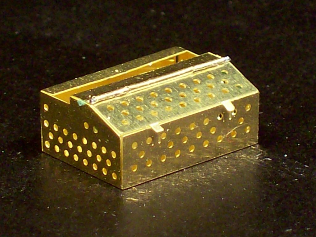
The lid is next and the hinge was formed using the same technique as in the "HINGE" section above.
100_0882.jpg


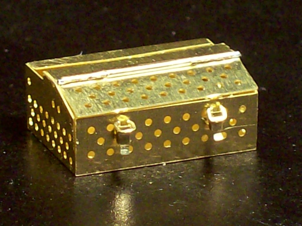
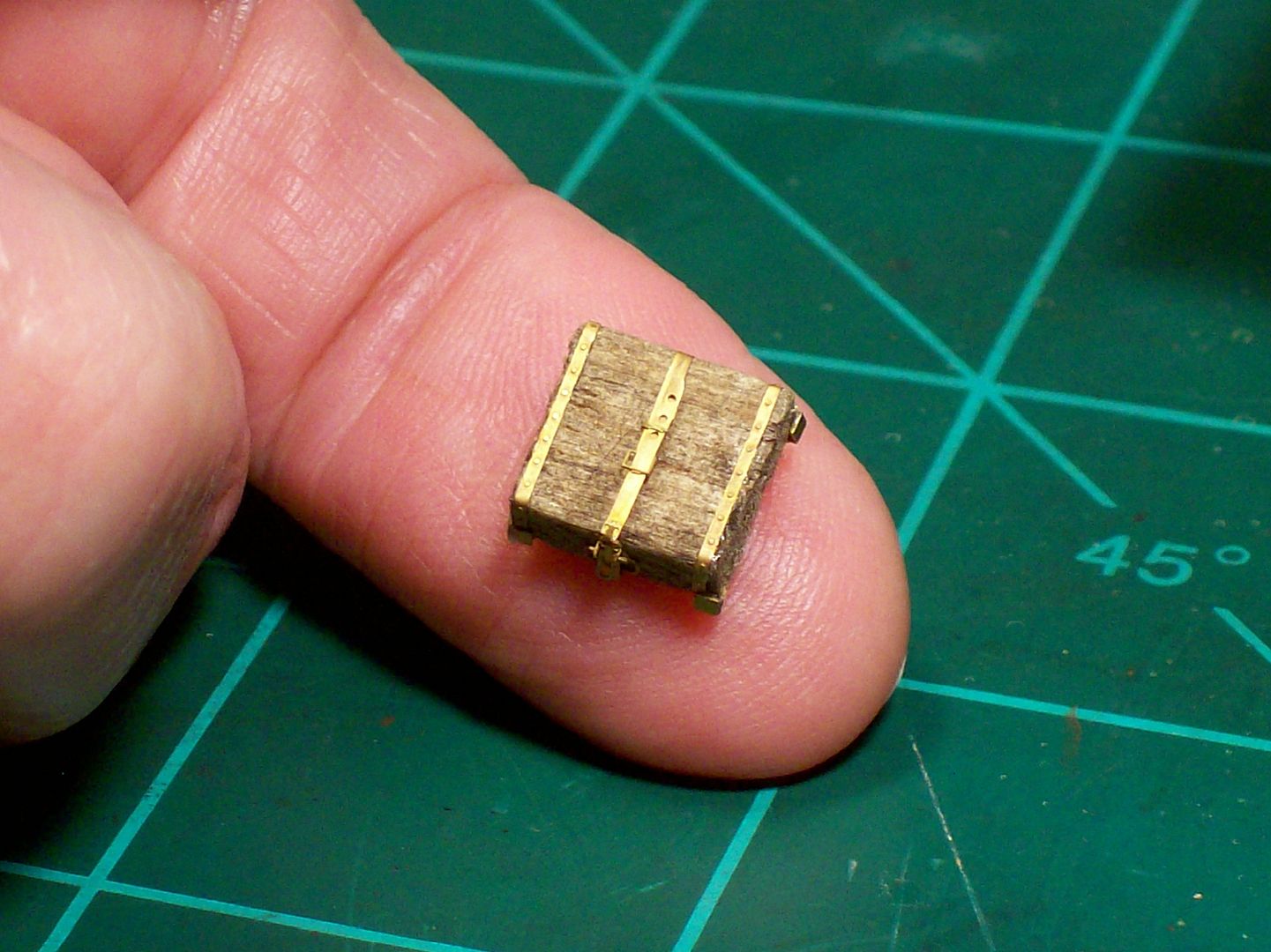
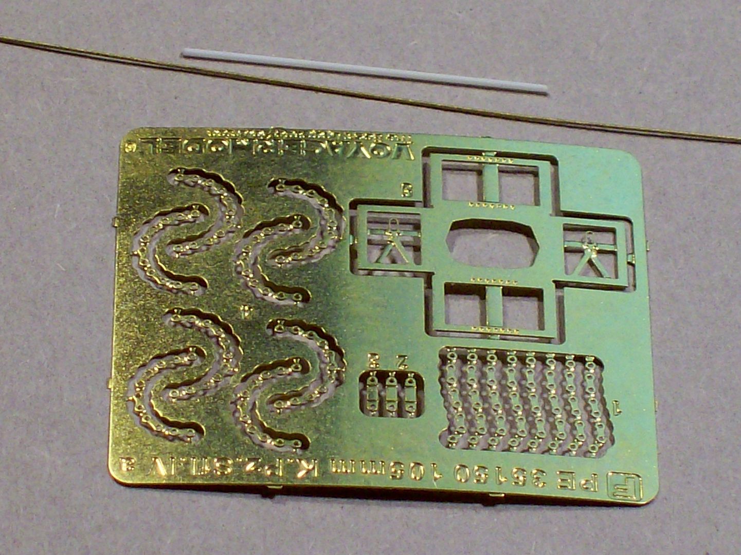
Next came the latches and man are they small.:eek:hmy: Optivisor #10 to the rescue.(y)
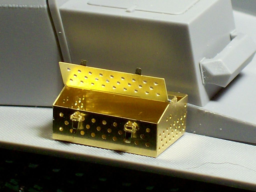
Since I want to open and close the lid I didn't latch the lid down.
100_0883.jpg


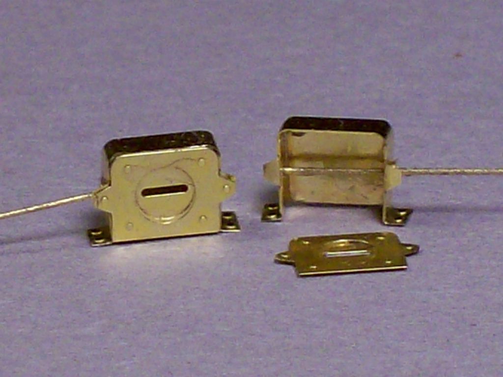
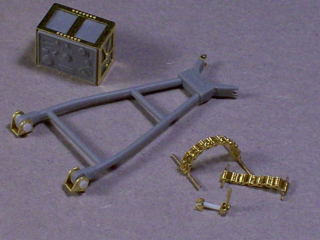
With everything assembled I applied a thin line of Gator Grip glue on each inside corners of the box and on each side top edge where the hinge plate sits and let it cure for awhile.
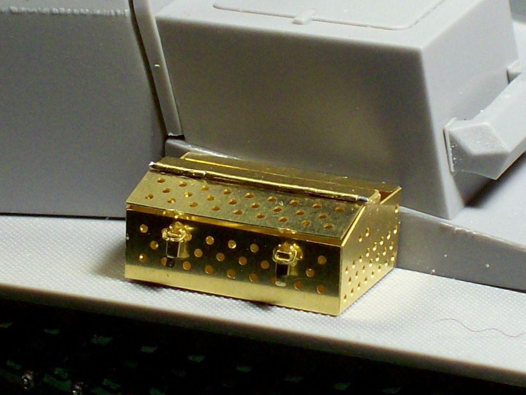
For scale I placed it on the fender of my Max to take the finished pictures.
100_0886.jpg

100_0885.jpg


Pretty good lookin box if I do say so myself.:lol:
I'm having fun,aren't you too?:woohoo:
Tony Lee:Hiay
 
TONY,

Go Dogg Go !!! What do you use to clean up your parts ? after you cut them free of th fret do you use a file, 800 grit sanding stick ? Just curious .... I use mostly a flat file just to take off any of the fret part that left.


Great Box ! :woohoo:


ERIK
 
Another excellent installation. I'm going to try your method of lining up just short of the lines. See if my folds are better. Cool. Tip.
James
 
Panzer guy,most of the time the 800 sand stick does fine because the brass is thin but on the thicker stock out comes the needle files.

Thank You Sir
Tony Lee:)
 
This is great stuff! I have two builds that are shelf queens because of not being sure how to make hinges. Thank you, thank you Tony (y) (y)

Tom
 
Hi Tony,

I saw the link to this Thread right after you posted it, but something got in the way and I didn't come here immediately and then I simply forgot about it: can you believe it?! :huh:

This is one excellent contribution to MA and specially for all those modelers for whom PE has to do with witchcraft - my case.
Emoticon_stirpot.gif
emoticon_veryaffraid.gif
For that I thank you as the other guys have done: I'm taking everything in slowly and with close attention, and will try some of your tricks'n tips on both my GB entries. ;)

You gotta admit it: your work with PE is daunting! :notworthy

Cheers and again, thanx! :dude
Fernao
 
Jack Blocks

One item that is common to just about all WW II German Armor kits is the Photo Etch parts to dress up the kits plastic blocks. The instructions require you to remove all the molded on detail and replace those with the brass items provided in the PE set.

I don't fool with filing or sand off the detail but use Balsa or Bass Wood. You don't need to simulate the wood grain since you're using real wood,a worth while benefit.
The block on the left is from an Eduard PE set and a Voyager PE set on the right.
100_0862.jpg

And in this case this one is also from a the Voyager set for my Emil.I cut the blocks from a stick of 1/8x3/8 balsa,two blocks are needed,one for each fender and all the PE bits cut from the sprue
100_0887.jpg


I stained the blocks with a thin wash of Raw Umber oil and the PE parts were glued on using Testors Wood and Metal glue in the GREEN tube.
The only tricky part is installing the latch handle pivots in the pivot bracket strap,the rest is a simple placement job.
100_0889.jpg


Compare the two components, the kit part and our replacement.
100_0891.jpg

The Trumpeter kit blocks have better detail than most and once painted up would look just fine but our real wood block just has that WOW factor you're after with very little extra effort.

100_0892.jpg


Have Fun with Photo Etch, don't fight it.(y)
Tony lee
 
Armored Head lights

These are for my DML Max and are part of the Voyager PE set. I thought you might be interested in another use of that dental pick we used to make hinges.
These are the kit supplied parts and would work just fine but the PE set has some that are a lot more detailed and sexy.
100_0898.jpg


I took a pre-fabrication picture but it vanished so let me see if I can fill you in on what I started with.
100_0900.jpg

Being flat the main body of the light is shaped somewhat like a "T". The top cross bar makes up the top and sides and the downward bar is folded to make the back.

First thing to do: The top corners are rounded and not square so you need to round the sides at the top to fit the curve of the back plate,here's where that dental pick comes in.
If you remember we curled up the hinge tabs using a dental pick, well we'll do the same thing here except apply more pressure at the joint of the sides and backing plate. I curled them up about 75% to 80% of the way to vertical and then finished them with my tweezers being careful not to flat spot the radius bend.

Now it's time to fold the back plate up to meet the sides. Use your tweezers to adjust the back and sides to form as tight a seam as possible. I used my Gator Grip glue to seal the joint seam,not a stress point and glue will work fine for this.
100_0899.jpg

The slot light covers were glued on the back side of the face plate.

After the glue had cured enough to hold, the base feet and the face plate mounting ears were folded.
I inserted brass wire to serve as electrical wire and the reinforcing gusset on the side then the face plate was glued on.
100_0901.jpg


TAaaaaDAaaaaa,a armored head light ready to mount on the fender.(y)

Thanks and class dismissed
Tony lee:)
 
HEY have you been talkin to my shrink? :hmmm

It must be a small world after all. :eek:hmy:

Thanks my friend
Tony lee :)
 
Thanks Tony,

Your thread gives me hope that my battle with PE isn't lost yet. You make it all look so easy.

Joe
 
Gun Tube Cradle

Here's something new for me and I thought it would be interesting to see what kind of mess I could make of it.:lol:
Have you noticed how the instructions make it look so easy but of coarse the diagram is blown up five times normal size.
100_0911.jpg

The PE parts plate:
100_0908.jpg


I drilled the frame and installed the base feet first and then went ahead and assembled one of the chain options,this is the one that goes over the tube while in travel mode. Not being sure what position I want the barrel to be in I just left the wire in each end for now.
100_0909.jpg

I put the two plastic kit parts there that are to be replaced with PE for comparison.

This is as far as i'm going to take it for now. Depending on when I make up my mind all that's left to do is install the handle on one end and attach the other end to the bracket on top of the frame work.
100_0912.jpg

The most difficult part for me was getting that wire through the handle and handle bracket only because it's so small and hard to hold onto.:gogo

As you can see the Photo Etch has that pizzazz that the plastic doesn't.:woohoo:
The plastic parts are just fine but I wanted to show off some.:blush: :lol:
Thanks for watching
Tony lee:)
PS: I went ahead and folded the radio frame work for later.
 
Back
Top