• Modelers Alliance has updated the forum software on our website. We have migrated all post, content and user accounts but we could not migrate the passwords.
    This requires that you manually reset your password.
    Please click here, http://modelersalliance.org/forums/login to go to logon page and use the "Forgot your Password" option.

Universal Carrier FINISHED

paddy

Well-known member
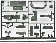
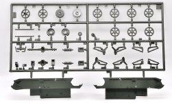
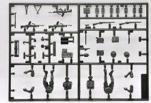
This is Tamiyas old kit of the Universal Carrier or Bren gun carrier.
Its labelled as a European Campaign model however i am not sure how it differs from a North African campaign version as it includes figures in short sleeves, tin hats and shorts as well as European cold weather fatigues as well as North African 7th armoured brigade decals. It may be that the NA version is the same kit in a yellow plastic rather than this black......which i think may be a very dark green ?
This is a 1976 kit and seems to have been re-boxed as a reconnaissance and also a radio command version as well as this Bren gun version over the years

DSC_1844.JPG


DSC_1846.JPGDSC_1847.JPGDSC_1848.JPGDSC_1850.JPGDSC_1845.JPG
DSC_1851.JPG


above is literally 10 minutes work but about as far a i can go without some painting. If you put the sides in the foreground on at this stage the interior will be hard to detail. this is a very simple kit, there are nearly as many parts to the 5 figures and their weapons as there are to the carrier itself so another speed build :)

cheers Paddy
 
Last edited:
A high rate production line you've opened there. Definitely a simpler kit than the Riich Carrier kits., they probably have more parts in the in just the tracks.

My uncle broke his leg jumping out of one the these while at Battle School, snagging the blousing of his trousers on a sticky out bit as he went over the side.

Cheers,
Rich
 
Maybe one of these figure should be hanging upside down by his trouser leg at the back to add realism :)j
 
This is the radio from the kit

DSC_1854.JPG


and the only picture i can find of the real thing.

universal-carrier-reading 2018-107w-3.jpg


Basically the same but staked rather than side by side. I need to make a wire frame obviously but i am not sure about that grey front panel ?? thoughts ?? what about the cylindrical thing under the set with the large control knob ?

By the way i have decided to go with a drab paint scheme so i can try something different from the desert scheme
 
If I'm not mistaken the smaller unit is actually the power supply. Interesting the difference in the mounting. Not going to say anything about the face, I'm sure someone's going to come up with the TO somewhere soon. That wireframe is to prevent butt dialing.
Can't even speculate the cylinder thing, should be fun to recreate though.
:popcorn
 
I think the cylinder is a modern addition, i would guess the large knob is some sort of rheostat so speed or voltage controller, the cylinder looks like a dynamo or motor, the end sticking out would be the brushes end so the cable is going in not out. possibly a charging device for the radio battery pack....................................but, i have found this which is more in line with what i have

T16RearOverhead.jpg
T16Wireless1.jpg


No cylinder but a lot more complicated frame work to make and interestingly still a grey control panel all be it a bit darker.
I think i will use this as my reference. Now is the kit radio usable of should i try and scratch a new one...
 
The earlier picture you had was a WS19 Mk III from a Ford built T16 Carrier, also known as a Windsor Carrier. It had some changes (30"inches longer, two 2 wheel bogies per side, different engine, lever controls in place of the steering wheel) and was often used as an artillery tractor.

The kit radio is a WS19 Mk II. In a Universal Carrier Mk II it was installed on the bulkhead behind the driver. In a Universal Carrier Mk I it was installed on the right hand track guard.


Carrier 066.jpg


Carrier.jpg


Carrier 036.jpg


The mystery cylinder is an Aerial Variometer. It began to be installed in 1942. The photos are from a Canadian restored carrier.

Aerial Variometer Mk II

Cheers,
Rich
 
Fantastic Rich, i see the variometer has turned up in the MkII in your pictures so maybe i need to include it after all
Many thanks thats great :)
 
Looks like your radio questions are all sorted out.

I would offer up, though, that the UC Mk II didn't enter production until 1943, so it's not very likely to have showed up with the Eighth Army in North Africa. It is just possible that some UC Mk II might have made it to Tunisia with the First Army. I don't have the Tamiya kit, but I suspect that the crew figures in khaki drill shirtsleeve and shorts are left overs from their earlier UC Mk I kit. At any rate, 1943 is when the UC Mk II saw its introduction.

Just in case you want to add the wiring for your No. 19 radio, here are some sketches that I made a couple of years back while working on a similar project. The gray color of the radio face is correct. It can be either a dull, aluminum or a light, slightly metallic mouse gray depending on the manufacturer. Most are the light gray, though. With age and use, many appear a darker, medium gray with brownish undertones.

This first sketch was done up for the Riich UC Mk I kit which includes the parts for the No. 19 radio set but doesn't provide any instructions for installing it. (The kit also includes a very nice No. II set witch is covered in the instructions.) If you ignore the kit part numbers (most prefaced with "K"), hopefully the rest will make sense.

Riich-Models-No-19-Radio-Se.jpg


This is a close up of the control unit No. 2 Mk II in my collection which the radio operator would route his headset through. There was no provision on the radio for the operator to plug directly into it (except for the No. 19 set fielded for ground-mounted use in HQ situations). So, you should add the control unit to your setup.

Control Unit 001.jpg
Control Unit 1 of 3.jpg


Note that the radio headsets and microphones all had these types of rubber covered "snatch" plugs. They are a very distinctive, black rubber double-cone shape. The cordage is fabric covered and varies in color from a light tannish color to a medium brown.

Control Unit 3 of 3.jpg


If you really want to go down the "rabbit hole" with more details, let me know, and I'll post up some more photos of the radios and antenna bases.
 
Thats great thanks Sd . i have actually gone with a European colour having researched it a bit so 42-43 is not a problem. I pretty much found the ministry's colour schemes and they there is a huge variety ranging from Brown because there was a shortage of the chromate used to turn the paint green in 40-41 right up to US olive drab in 1945, with camo light brown and dark brown, British kaki drab and British green drab in-between years.
TBH while its nice to get things right its also about having fun . Interesting you Ariel rheostat is marked as "on wall" all the pics i have found have it on or under the radio.

Yes, the Variometer (what would now be called an antenna matching unit) is mounted in a different location in the initial WS No. 19 installation in the UC Mk. I. This initial install replaced or superseded the WS No. II that would have been in most earlier carriers.

Here's an illustration from the install manual for the earlier procedure. The Variometer is item no. 8, and its mount is item no. 25 in the callouts. Even without the rest of the page and manual, you can identify this carrier as the Mk. I by the rectangular (wood or hard rubber) firing rests around the top edges of the compartment. The UC Mk. II and III had these replaced with split, round metal tubing sections.

UC-Mk-I-WS-No19-Radio-Install-Layout.jpg


It was all a very tight fit, especially when squeezing in the radio operator, too. Here's an in progress shot of my Riich UC Mk. I build dry fitting in the No. 19 set and the converted RTO.

UC-Mk-I-WS-No19-Radio-Riich-Kit-Build-02.jpg


You can see the Varimoter on the wall behind his right shoulder. (The fixture with the hook is the radio mount originally issued with the WS No. II which allowed the mast aerial to be folded down to the rear. This feature was mostly disabled when the WS No. 19 was installed and the aerial was just kept in the upright position.)

Here's another shot of the completed vignette with the RTO figure and WS No. 19 in place. You can see why, with the super tight fit that the later WS No. 19 installation was modified to put the radio at the front of the compartment.

UC-Mk-I-WS-No19-Radio-Riich-Kit-Build-01.jpg


BTW, the finished vignette displays the top of the engine compartment separated from the carrier to show off the Ford Flathead V8 engine included in the kit. The vignette represents a Canadian UC Mk. I of B squadron, 4 PLDG, 1st Canadian Infantry Division ca. September 1943 during the exploit phase of Operation BAYTOWN, the invasion of southern Italy.

Any hoo... There is a difference in how the WS No. 19 components were initially fitted in the UC Mk I and then in later installations in Mk. I, II, and III UC's. The components, themselves, remained essentially un-changed, to include the cabling and accessories.

Happy modeling!

Mike (yes, another "mike"... LOL!)
 
Yea thanks mike
the problem i have is all the restored versions are different, in post #8 above the switch unit on the bulkhead is wired straight into the bottom left of the radio. much like your diagram, the model above the switch unit is wired in the variometer and the Arial is wired in to the bottom left of radio :)
I have been unable to mount the switch unit where i think it should have been because the bulkhead in the kit is not big enough to take it.
For this reason i am putting the parts where i think they would fit but its not going to be technically correct.
DSC_1872.JPG
 
Back
Top