• Modelers Alliance has updated the forum software on our website. We have migrated all post, content and user accounts but we could not migrate the passwords.
    This requires that you manually reset your password.
    Please click here, http://modelersalliance.org/forums/login to go to logon page and use the "Forgot your Password" option.

Trumpeter 1/35 M-1078 FMTV w/ Softside cab

Adam Baker

Active member
Got this kit from Saul, to do a build review, and then he posted up a pic of the truck w/ a face drawn on it and suggested building it at part of the Face It campaign, so here I am!

This is actually a combination of 2 kits.

The 2 wheel chassis is part of the M-1078 uparmored FMTV kit, w/ the soft side/unarmored cab from the 3 axle M-1083 kit.

M-1078 Kit

TrumpeterM1078ArmorBox.JPG


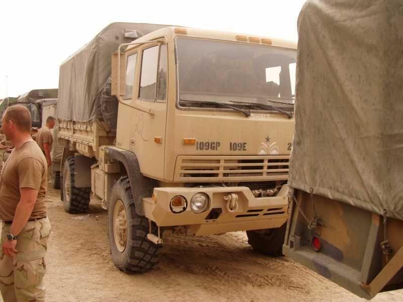
Pic of the real thing w/ the face.

M-1078withEyes_zps0a35b05d.jpg


And then the requisite time stamp shots.

M1078-002_zps43feea64.jpg


M1078-004_zps10520c5b.jpg


The instructions have you start by building the frame, but since its separate frame rails w/ cross pieces, I decided to start by building the pieces that span the frame, prior to building the frame, so that I could attempt to make sure that the frame was straight & square, so that all 4 wheels touch the ground.

M1078-010_zps37496034.jpg


I also started assembling the cab, to help keep everything square.

M1078-014_zpse79c4477.jpg


Once that was done, I started working on assembling the frame.

M1078-018_zps32d68991.jpg


M1078-020_zpsd3a24096.jpg


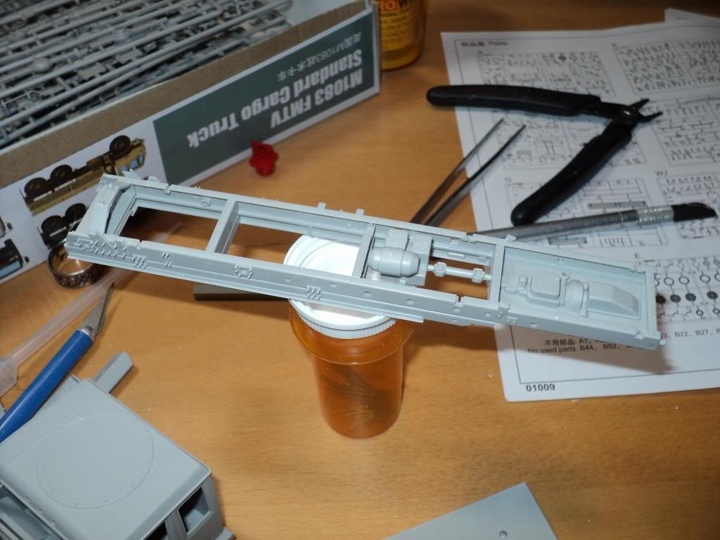
And here the frame is completely assembled.

M1078-020_zpsd3a24096.jpg


M1078-021_zps929e18d2.jpg


I've started working on the suspension components so that I can assemble the whole suspension in a single go, to ensure as much as possible that all 4 wheels will touch the ground.

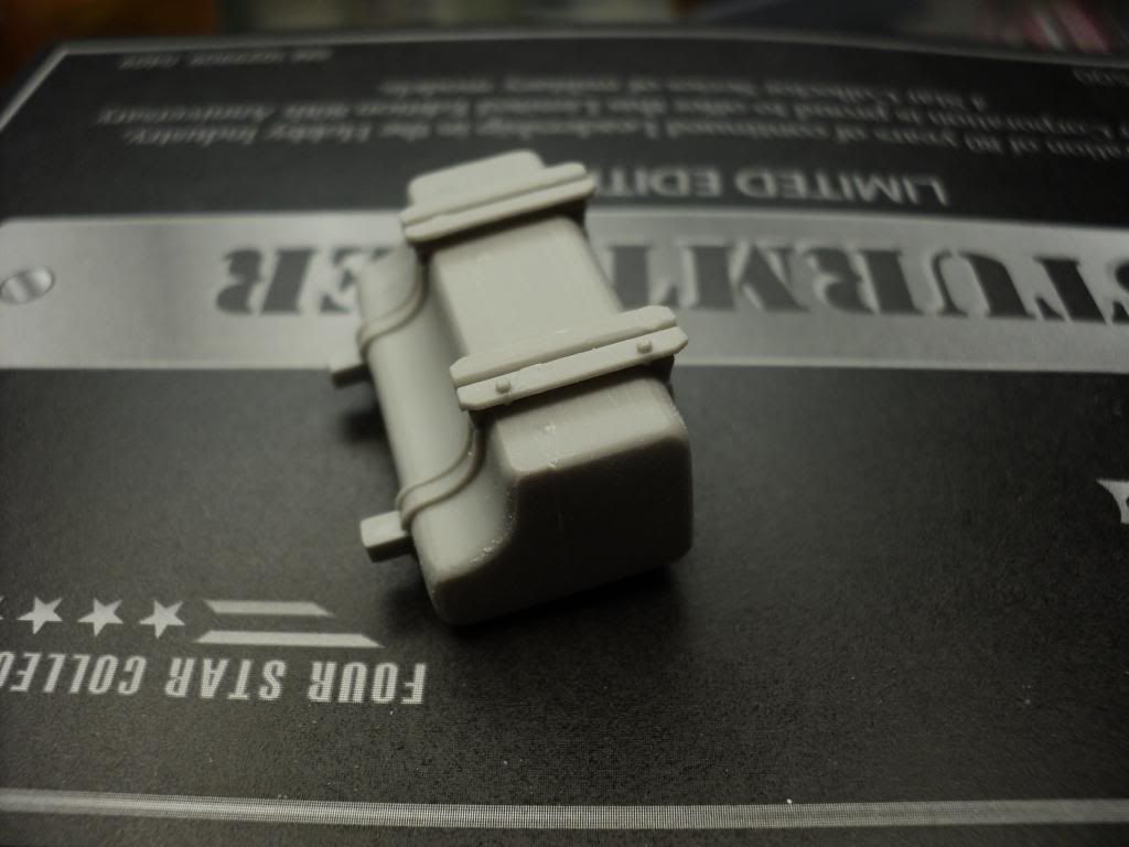
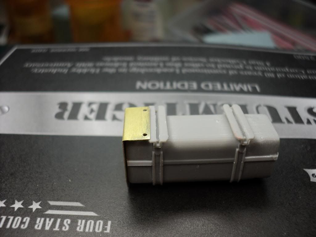
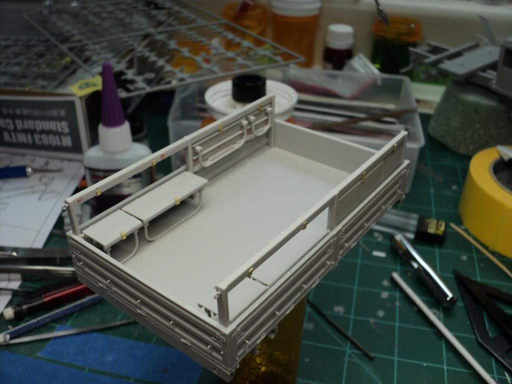
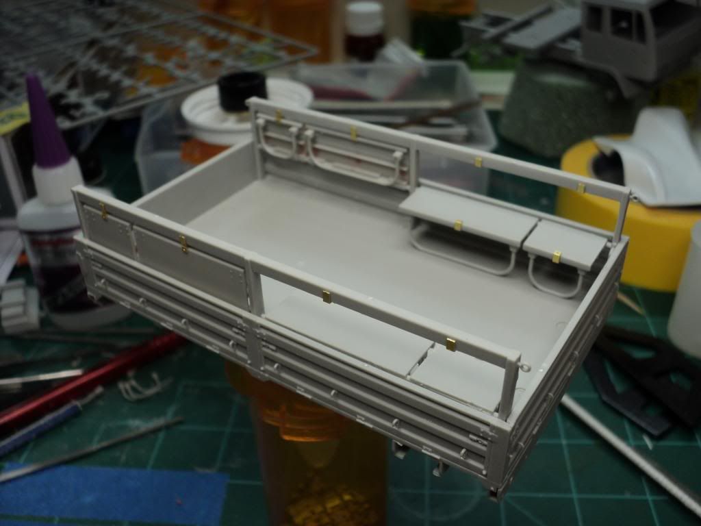
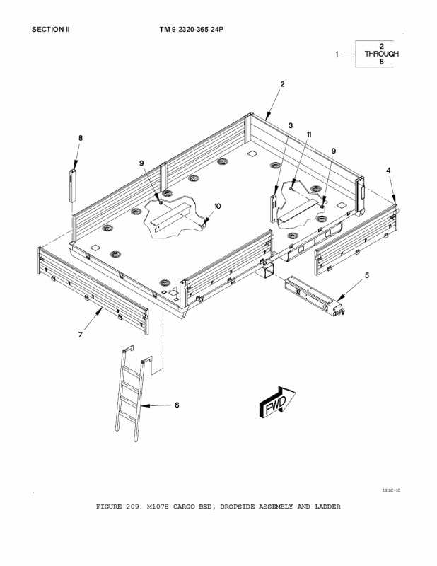
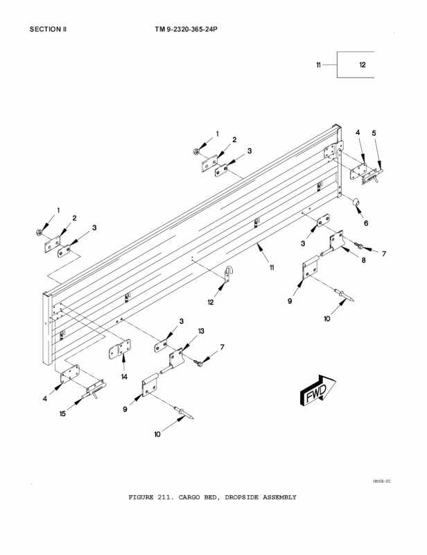
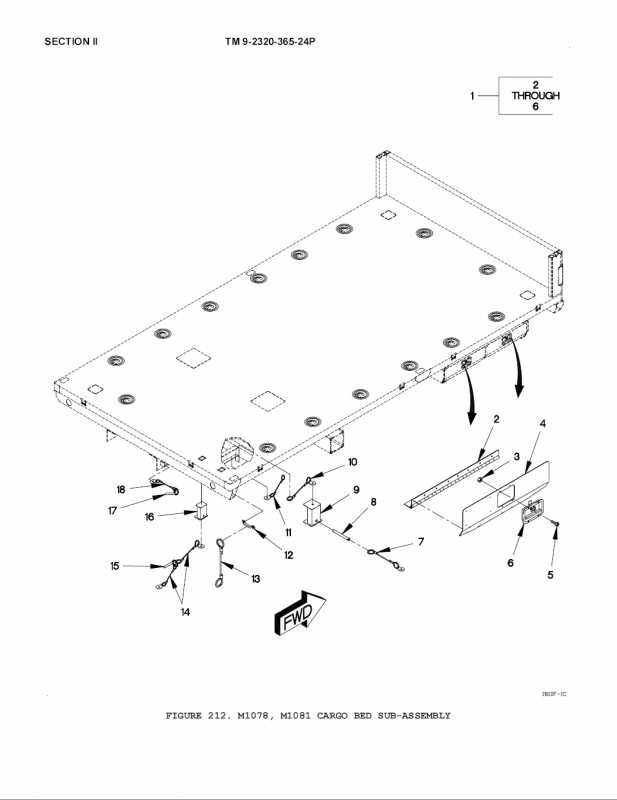
I've also started looking at the cargo bed. The kit doesnt come w/ provisions for the canopy over the bed, but I dont think it would be too incredibly difficult to fashion the frames & the canopy. The kit also comes w/ an option for the troop seats in the bed, either in the up or down position, so I'm thinking about maybe doing it half & half. One side willl have the seats up, and the other side will have the seats down. Thinking about maybe putting some cargo in the bed w/ a couple soldiers sitting on the seats.

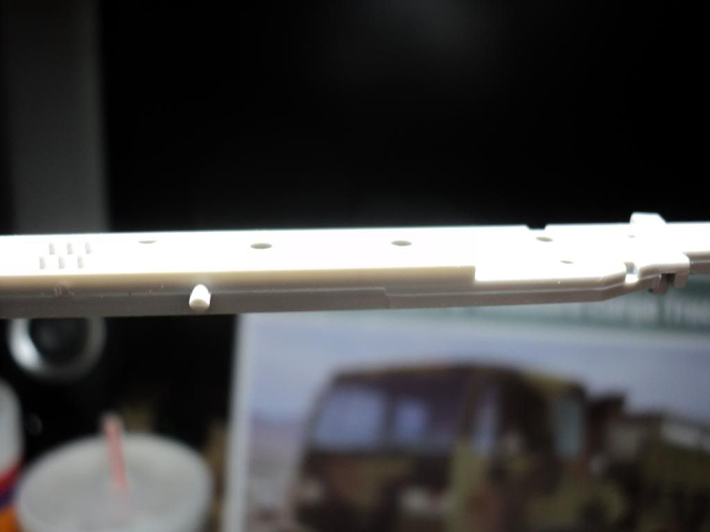
So far I'm impressed w/ the kit. Its the first Trumpeter kit I've worked on. Fit so far has been very nice, w/ no real issues as far as fit is concerned. I have noticed that the mold seams are a bit heavy in places, w/ the frame rails so far having the heaviest seams I've had to deal w/.

Here's a picture, but its not the best. I was at my mom's place this weekend, so didnt have my photobooth or anything w/ me to help get better pictures.

M1078-008_zpsa1a73287.jpg


M1078-007_zpsf449fad8.jpg


There is an abundance of punch marks, but the vast majority seem to be placed in areas that either wont be seen at all, or are in places that are difficult to see. The most visible punch marks are on the insides of the cargo bed sides, but thankfully they're fairly small and should be easily dealt w/ by using punched .010" styrene disks that I can sand flush.
 
You know I am watching!

I think I mention that I have all the manuals but hopefully, you won't ask so I won't bog you down with details!

Regards,
 
Haha, I've been trying to decide if I was going to add any details to these or not. if it had a full engine, I'd seriously consider it. The company I work for makes most of the cooling package for these things (radiator, oil cooler, intercooler for the turbo, etc). The thought I'd had was to do it like in a maintenance scene where the engine was exposed w/ all the parts my company makes being visible too, but since its just a curbside w/ only the bottom of the engine molded, I didnt bother.

At this point, I think the only real extra stuff I'm going to attempt, is the bracing for the cargo cover. If you've got anything that covers that aspect, I wouldnt mind taking a look at it.
 
Im referring to the hoops that go over the top, to support the cargo cover. I dont see anything in those images that shows the hoops at all.
 
Well, nothing really to report in the last week. I've got a little bit of work done on the suspension, but this week has been really busy w/ other things, including some family stuff that came up late last week that took a lot of my time. Hopefully I can get a lot more done this week.
 
Finally some measurable progress to post.

This evening I got the rear suspension assembled and attached to the chassis, and I have to say IMO the method Trumpeter chose for mounting the suspension just sucks.

Here's an overall shot of the assembly.

M1078-028_zpsc3f953b6.jpg


At the corner of the leaf springs, they sit into the shackles attached to the frame. The shackles have little molded in bumps that mate w/ holes in the leaf springs at the front, and the leaf spring hangers at the back. And to get the bumps into the holes, you have to force the pieces into place, which is just a recipe for disaster. Every single shackle distorted slightly during the assembly, and the hangers at the rear end of the leaf springs started coming apart. The hangers are 2 pieces that are joined together, w/ a pin on each side going through the leaf spring. The instructions say to make sure to not get glue on the hanger/leaf spring joint, so that the hanger is loose/floating in place so that you can attach the hangers to the shackles.

Here you can see the hangers in the shackles.

M1078-030_zpsac4abc98.jpg


I was able to get it all together, but it was some very tense moments trying to force the pieces together. I'm not entirely sure what I'd to to get around this problem any other way. I'd almost think about drilling out the rivet heads on the shackles and going w/ a piece of styrene rod in its place, just so it wouldn't have to be forced in place. And then going w/ a piece of hex rod to replace the removed hex or go w/ a cast resin bolt head.

I did learn one important thing w/ assembling the rear end. There is a sway bar that is attached to the rear axle, which is then attached to 2 pieces coming off the frame. The sway bar should most likely be left off until the rear axle is in place. The kit simulates the U-bolts that hold the axle to the leaf springs, and if you insert the sway bar too far into the axle (like I did) then you cant get the U-bolts in place correctly, and the sway bar will be too close to the axle and wont mount on the 2 pieces coming off the frame.

You can see the sway bar here, and how its not touch the rear axle like it should. I had to break the sway bar loose to get everything to mount correctly.

M1078-032_zps7608be22.jpg


I'll be moving on to the front suspension next. Hopefully it goes together better than the rear did.
 
I saw you asking about the suspension on some other sites...

I will pay attention to see what comes your way in responses.

Regards,
 
Yea, I posted on Missing Lynx about the front suspension, which is as bad, or worse, than the rear. It attaches differently, so it has all its own problems to deal w/.
 
Unfortunately no progress this week, forgot to post up my update the other night. Been super busy w/ my freelance design work this week, and what little time i had for building, I spent on other builds.
 
Lots of progress in the last few days.

Biggest piece of progress in the last week was figuring out what was wrong w/ the front suspension. I'd been having a bear of a time getting it to go together. This is what it looked like when I was trying to glue it in place.

As you can see, the base of the leaf spring hanger didn't line up for squat, and to make it even worse, when trying to force them in place, it caused the leaf springs to flex quite a bit, and then the leaf springs would hit one of the frame cross members. I knew this wasn't right, but I couldn't for the life of me figure out what was wrong.

M1078-034_zps9beaa7be.jpg


M1078-035_zpscbc98819.jpg


The other night, after trying to figure out what was wrong, I started looking at reference pictures, and also a thread on Armorama where a guy built up a test shot of this kit, and I noticed in a couple of pictures how the suspension was put together, and I realized that I'd forgotten to included a couple of parts, and that was what was keeping it from assembling correctly.

There are hangers on the rear ends of the leaf springs, both on the front and the rear suspension. I'd assembled the rear correctly, but forgot the hangers that you can see below, when I was assembling the front. I had to pull the shackles off the leaf springs an insert the hangers. Once I did that, the suspension went together perfectly. The whole problem was operator error.

M1078-041_zps8804b45e.jpg


Once I had the suspension figured out, I started working on the various sub-assemblies. There's a air bottle assemble on the left side of the truck, and the fuel tank is located on the right side. The air tanks are a fairly straight forward assembly.

The fuel tank required a fair bit of work to get cleaned up. Its 3 separate pieces, resulting in some nice large gaps to be cleaned up. Unfortunately I forgot to take a picture of the tank prior to the clean up, but I think it came out pretty good after sanding the seams down. One thing I'm working on now, and don't have pictures of, is replacing the molded on tank seam across the front of the gas tank. That raised section in the middle I'm assuming is the joint when the real tank is joined top & bottom, and that is where the top & bottom halves of the kit pieces meet, leaving a large step that has to be taken care of, and I ended up chiseling off the raised portion so that I could clean the seams. I've gone back and put on a piece of .010" thick styrene to help simulate that line. I think it looks pretty good so far, but it needs some clean up.

M1078-037_zps56b1b20f.jpg


M1078-038_zps36f03374.jpg


Once the tank was assembled, I had to put the frame mounts on the bottom, so that I could attach the photoetch shield, and this is where I ran into another problem. One of the 2 frame mounts has 2 posts, that correspond w/ 2 holes in the shield. I found that the posts were larger than the holes in the shield, so I drilled the holes in the shield out using a .035" micro drill, so that the posts would fit. And then the 2nd problem showed up. The posts on the frame mount are closer together than the 2 holes in the shield so I planned on just cutting a single stud off, and using the other to align the shield in place. And then the 3rd problem w/ this shield came up. After bending the shield at the relief joint, I found that the bottom section of the shield was too short to reach the remaining stud on the frame bracket. So because of this, I ended up just cutting the posts off of the frame mount, and when I'm ready, I'll just superglue the shield to the frame mount and call it good.

Here you can see the studs.

M1078-050_zpsb7cc6c83.jpg


And this is the shield piece w/ the holes. The holes had to be made larger so the studs could go through.

M1078-051_zps046015be.jpg


But here you can see that the studs don't match the holes. Just for sake of clarity, the shield is laying on the tank in the opposite direction that it would actually install, but it was easier to get the picture this way.

M1078-053_zps1690ec7b.jpg


Here you can see the bent shield, and how it just barely lines up w/ the edge of the frame bracket. In this shot I've already cut off the alignment studs.

M1078-055_zpsc9cfa034.jpg


The last thing I worked on was what appears to be a small auxiliary fuel tank of some kind, that's located next to the air tanks on the left side of the truck. This piece also has a shield on it, similar to the shield on the fuel tank. Thankfully this one went together much easier than the fuel tank.

Here's the assembly.

M1078-057_zps62b7864b.jpg


And how it sits in the truck.

M1078-059_zps6cd54ecf.jpg


The shield actually attaches to the bottom of hte air tank assembly in a small lip, seen here

M1078-061_zps02042472.jpg


And that's it for now! I think the next steps will be to finish cleaning up the bed components, and then assemble the bed. I'm still undecided on how I want to display the cargo bed. The kit gives the option of displaying the 8 troop seats either in the stored position, or in the deployed position. I've been thinking about doing 3 or 4 in the down position, and the rest up so that I can put some kind of pallet in the bed.
 
Just a quick update, but its starting to look like a truck! Got the bed assembled tonight.

M1078-064_zpsbad5b870.jpg


Fit is pretty decent from what I can tell so far, but I've only assemebled the sides and the bottom. The upper rails that are visible are what hold the troop seats, and they're only just sitting in place. I've already sanded off all the mold seams, which were kinda large, but not too bad.

The biggest issue I ran into w/ the bed assembly so far is that the inside of the bed panels have some rather prominent punch marks, which unfortunately are a bit small for my preferred method of filling punch marks, which is using punched styrene disks. Thankfully most of them that are visible once assembled, aren't too deep, so I was able to blend them in w/ a sanding stick. The rest that are visible I'm hoping to hide. My plan is still to put some kind of load in the bed, w/ a few troops sitting back there as well, so I can use equipment & such to hide the punch marks.
 
Thanks Bob. Its definitely coming together, and I'm liking it. So far except for a couple minor hiccups on my part, this has been a pretty easy build.
 
Weekly update is a bit late, sorry about that. Unfortunately no progress this week. Thought I was going to get to this one but just never did. Been spending most of my bench time focusing on a couple other builds that are close to finished.

Hopefully at some point this weekend I'll work on this one and I'll post an update.
 
A lot of progress today. Was off for the 4th, and spent most of it at my bench, been awhile since I've done that.

Started off by assembling the jump seats in the bed. The seats have 2 optional positions, deployed or stowed. I decided to go w/ half the seats in the folded down deployed position, and half of them folded up in the stowed position. My plan is to put some kind of cargo in the bed and hopefully put a couple of figures as well, so I thought this would work out well.

Each seat is made of the seat itself, and then its leg. There are 2 legs for each, w/ only one of them being used, determined by its stowed or deployed configuration. Then each seat also has a photoetch buckle, w/ a corresponding buckle on the seat frame.

M1078-069_zpsee9f4438.jpg


M1078-070_zps33a8b248.jpg


Assembly was pretty straight forward, just clean things up and glue the appropriate leg to the seat, and then glue it to the frame. Unfortunately the seats have some pretty large punch marks on the bottoms. If the seats are in the deployed position, then its not an issue. But if any of them are folded up, then they are extremely noticeable, and pretty difficult to deal w/. I ended up filling them w/ putty, and then using sanding sticks and files that would fit between the rails of the seat frame. The end result was good IMO, but it would have been a lot nicer if Trumpeter had engineered it so that they weren't there in the first place.

The biggest problem I ran into while assembling the seats, is the fact that the photoetch buckets aren't wide enough for the seats or the seat frame. What I ended up doing was folding one side of each buckle up, applying superglue to it, and getting it positioned correctly. After giving it time to dry, I'd put a dot of superglue on the 2nd side and then fold it up into place. This resulted in getting the buckles where they needed to go, but took extra work that I don't feel should have been needed if the photoetch had been sized correctly for the plastic parts.

Once the seats were done, I then moved on to what I hope is the most tedious portion of the build. Around the outside of the bed, are 26 individual tie down hooks. Each one has a slot it fits into, and lets just say it wasn't much fun. However, amazingly enough, I managed to get all 26 hooks in place w/o shooting a single one out of my tweezer's and into oblivion. However, if one had gotten lost, the kit supplies 32 of them, so thankfully there are 6 spares, just in case.

M1078-072_zps6f3dab19.jpg


The other thing I worked on today was the frame work underneath the bed that sits against the truck frame. It was a pretty straight forward assembly, that went together quickly. The only thing I gave special attention to, was the boarding ladder that hangs from the bottom. I read in other build threads on the internet that the ladder doesnt seem to fit in the brackets designed to hold it. So I sanded down all sides of the ladder to make it slightly thinner, and then using a thin file, I cleaned up the tracks that hold the ladder. Once assembled, the ladder slides in & out of its frame w/o any issues at all.

M1078-074_zps896f8203.jpg


And how it looks on the truck.

M1078-068_zpsef093e53.jpg


Getting closer!
 
Back
Top