
-
Modelers Alliance has updated the forum software on our website. We have migrated all post, content and user accounts but we could not migrate the passwords.
This requires that you manually reset your password.
Please click here, http://modelersalliance.org/forums/login to go to logon page and use the "Forgot your Password" option.
You are using an out of date browser. It may not display this or other websites correctly.
You should upgrade or use an alternative browser.
You should upgrade or use an alternative browser.
I-16 Type 17 in 1/32, OD's Mulligan
- Thread starter Old Dog
- Start date
Heavens Eagle
Well-known member
This should be an interesting build Gary! Am slowly coming around to the WW2 Soviet aircraft.
Be sure to treat it like a Gremlin, no bright light and don't feed it after midnight.
Be sure to treat it like a Gremlin, no bright light and don't feed it after midnight.
Old Dog
Well-known member
OK, before I get too deep into this I'm going to make a few comments about the kit and my plans for it. First of all it's a Special Hobby kit, read limited run technology, soft details, flash, lots of mold separation seams on the smaller parts, for the most part no alignment pins and the usual rather vague instructions.
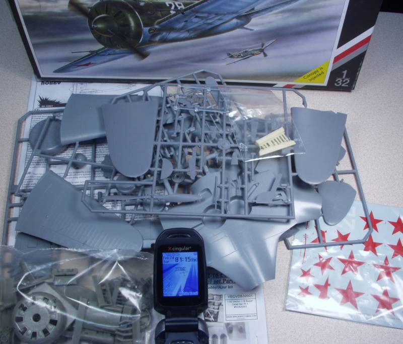
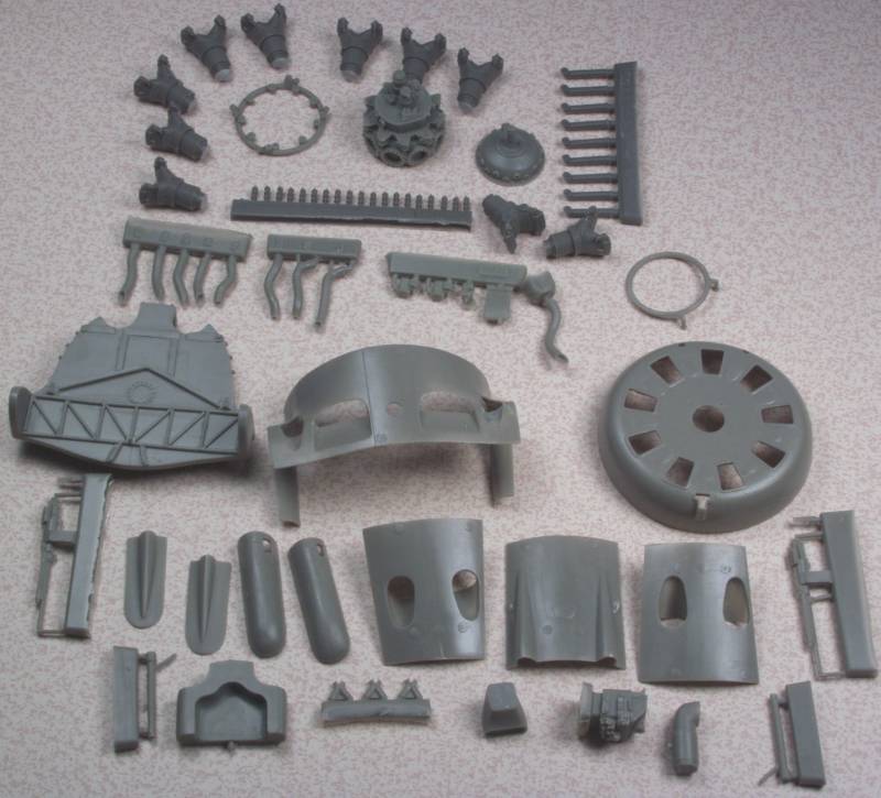
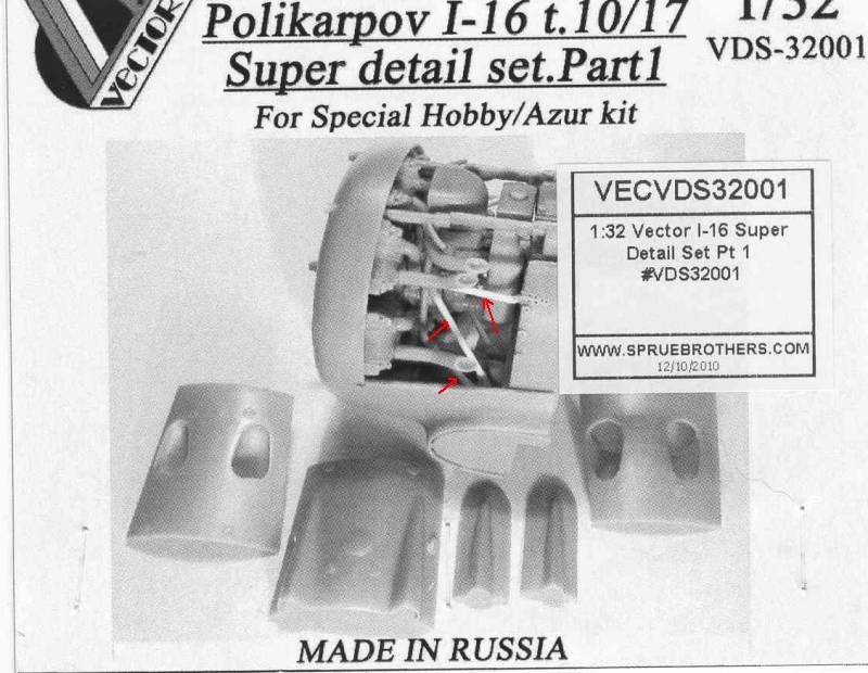
The Vector detailing kit is expensive, I may have paid more for it than I did for the kit. Although I did not count, it may have more parts to it than the rest of the kit does especially as some of the kit parts are for other versions and also includes ski options for the landing gear. The photo below shows what comes with the Vector set, besides the lovely engine parts you get basically everything from the fire wall forward except the propeller and spinner. It also includes a nice pair of machine guns and blast tubes. I'm not usually one who likes to display a kit with its guts showing but I may make an exception in this case. In the photo most of the parts have been removed from the pour blocks except for the ones that are numbered and I need to keep track of.
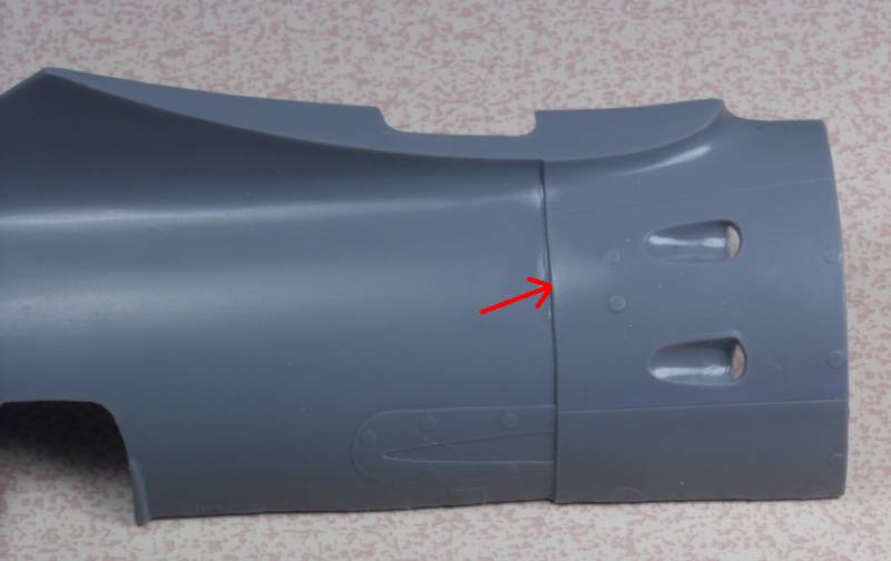
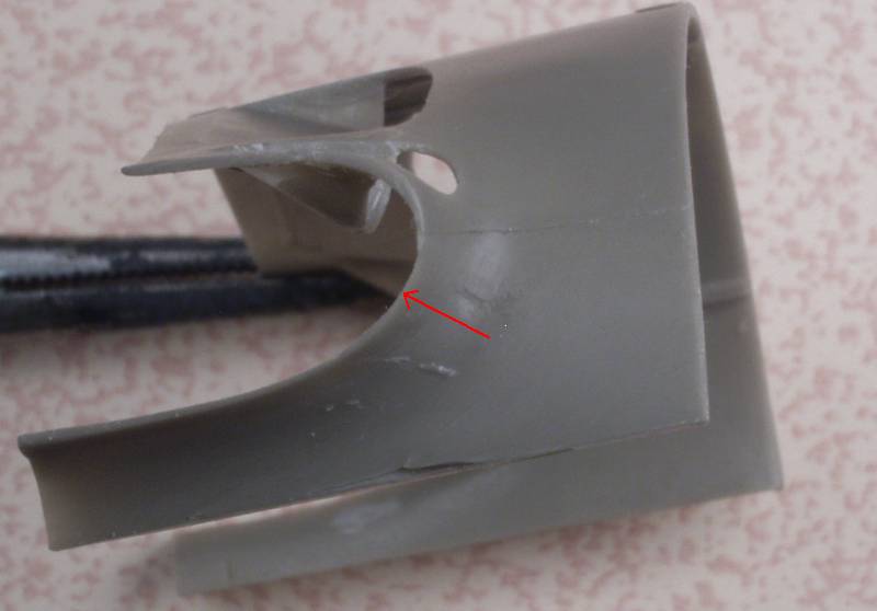
Now in order to use all of this there will be some surgery required. The forward part of the fuselage will need to be cut off at the line indicated by the arrow.
Also the forward part of the lower wing center section needs to be cut away where the red lines are located.
I'm probably going to wait until the fuselage halves are together before cutting them, I want to make certain that the lower wing center section fits correctly, test fitting to date indicates I may need a spreader bar to make this happen.
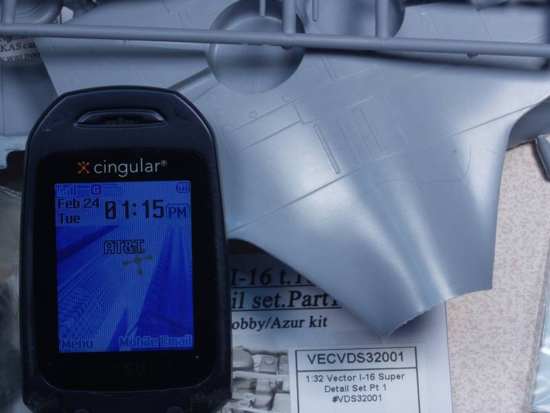
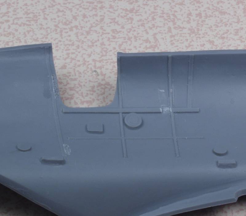
At the time I bought this kit I could not find an Eduard set for it. I'm glad I didn't as it would have been a waste of $$. The pit is a black hole. As can be seen in the photo below, even with the pit access door not installed, unless a light is put in there, not much is going to be seen , not that there is a lot to see anyway.
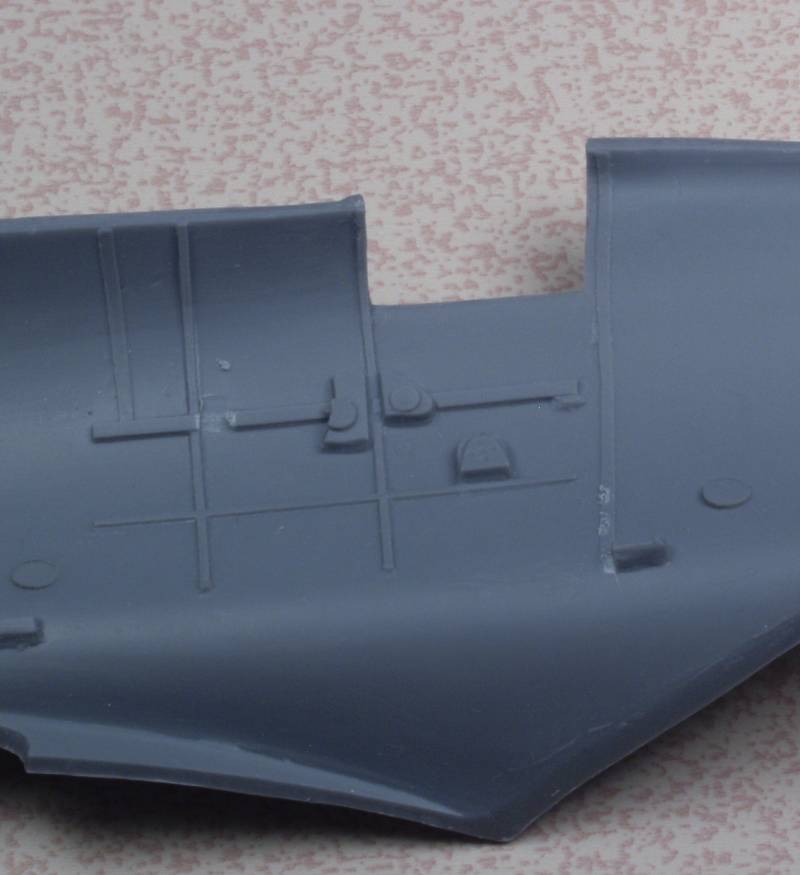
And as usually the instructions are not much help in locating what does go in there. I could find no obvious place to mount the instrument panel and resorted to looking at the instructions for the Eduard 1/48 scale kit to figure it out. It sits so far back under the cowl that even my pathetic attempt to paint it by hand won't be seen. As can be seen in the photos below, both sides have some structural detail, the round blob on the port side is where the throttle quadrant should be and I'm going to add some levers there, on the starboard side one of those blobs is where the hand crank for the gear is mounted and I'm going to add that the other blobs also have either cranks or levers, we'll see what happens when I get there. The notch chiseled out of the frame on both sides is where I think the instrument panel is supposed to set.
So there you have it, next comes painting the interior parts and the usual WTF colors do I use here routine and getting started on the engine. Stay tuned !
The Vector detailing kit is expensive, I may have paid more for it than I did for the kit. Although I did not count, it may have more parts to it than the rest of the kit does especially as some of the kit parts are for other versions and also includes ski options for the landing gear. The photo below shows what comes with the Vector set, besides the lovely engine parts you get basically everything from the fire wall forward except the propeller and spinner. It also includes a nice pair of machine guns and blast tubes. I'm not usually one who likes to display a kit with its guts showing but I may make an exception in this case. In the photo most of the parts have been removed from the pour blocks except for the ones that are numbered and I need to keep track of.
Now in order to use all of this there will be some surgery required. The forward part of the fuselage will need to be cut off at the line indicated by the arrow.
Also the forward part of the lower wing center section needs to be cut away where the red lines are located.
I'm probably going to wait until the fuselage halves are together before cutting them, I want to make certain that the lower wing center section fits correctly, test fitting to date indicates I may need a spreader bar to make this happen.
At the time I bought this kit I could not find an Eduard set for it. I'm glad I didn't as it would have been a waste of $$. The pit is a black hole. As can be seen in the photo below, even with the pit access door not installed, unless a light is put in there, not much is going to be seen , not that there is a lot to see anyway.
And as usually the instructions are not much help in locating what does go in there. I could find no obvious place to mount the instrument panel and resorted to looking at the instructions for the Eduard 1/48 scale kit to figure it out. It sits so far back under the cowl that even my pathetic attempt to paint it by hand won't be seen. As can be seen in the photos below, both sides have some structural detail, the round blob on the port side is where the throttle quadrant should be and I'm going to add some levers there, on the starboard side one of those blobs is where the hand crank for the gear is mounted and I'm going to add that the other blobs also have either cranks or levers, we'll see what happens when I get there. The notch chiseled out of the frame on both sides is where I think the instrument panel is supposed to set.
So there you have it, next comes painting the interior parts and the usual WTF colors do I use here routine and getting started on the engine. Stay tuned !
Heavens Eagle
Well-known member
Quite interesting Gary! The Vector set does have quite a bit of stuff to it. As you said it looks like the 'pit is a black hole but putting nothing in there would get noticed.

phantom II
Master at Arms
Watching with interest
Cheers, Christian B)
Cheers, Christian B)
I'm with you Gary, I could enjoy building up those Vector engines all by themselves.

Old Dog
Well-known member
OK, I squirted some colors on the interior parts and while waiting for them to dry down decided to start on the engine.
I got the cylinders attached to the crankcase and then looked over the remaining bits to decide what needed to go on next. It was at that point I realized that they wasn't an obvious way to mount the engine to the firewall. Vector certainly spared no expense when they produced the instruction sheet shown below. After some study it dawned on me that the one tubular piece, marked with an arrow in the upper left hand box is actually a mounting ring for the engine with 8 stubs that would have been attached to tubes that then attached to the firewall. A look at the bottom left hand box shows 3 'Y' shaped fittings that mount to the firewall, obviously the mounts for the other ends of 6 of the support tubes. Apparently one is to use styrene rod to create the connecting tubes, and this can be seen on the photo that was on the kit label. In that photo it shows the other 2 tubes going to the mounting points near the top of the firewall.
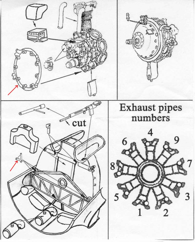
I suppose this would be doable but all the joints would be butt joints and even if one were to drill and use brass or some other material it would all be very fiddly and trying to get the engine perfectly centered and plum and seemed like an exercise in frustration to me. From the photo it's obvious that even with the panels off very little will be seen of the engine accessory section. The carburetor and oil tank effectively hide most everything behind the engine.
My thought is to create a solid engine to firewall mount and attach the engine. The circular flange above the girder on the firewall appears to be pretty close the engine center and would make a good mounting point. Then I could measure and cut all the support tubes which would then appear to be doing their job with a whole lot less hassle. That's my plan anyway.
I got the cylinders attached to the crankcase and then looked over the remaining bits to decide what needed to go on next. It was at that point I realized that they wasn't an obvious way to mount the engine to the firewall. Vector certainly spared no expense when they produced the instruction sheet shown below. After some study it dawned on me that the one tubular piece, marked with an arrow in the upper left hand box is actually a mounting ring for the engine with 8 stubs that would have been attached to tubes that then attached to the firewall. A look at the bottom left hand box shows 3 'Y' shaped fittings that mount to the firewall, obviously the mounts for the other ends of 6 of the support tubes. Apparently one is to use styrene rod to create the connecting tubes, and this can be seen on the photo that was on the kit label. In that photo it shows the other 2 tubes going to the mounting points near the top of the firewall.
I suppose this would be doable but all the joints would be butt joints and even if one were to drill and use brass or some other material it would all be very fiddly and trying to get the engine perfectly centered and plum and seemed like an exercise in frustration to me. From the photo it's obvious that even with the panels off very little will be seen of the engine accessory section. The carburetor and oil tank effectively hide most everything behind the engine.
My thought is to create a solid engine to firewall mount and attach the engine. The circular flange above the girder on the firewall appears to be pretty close the engine center and would make a good mounting point. Then I could measure and cut all the support tubes which would then appear to be doing their job with a whole lot less hassle. That's my plan anyway.
Ran into the same thing with the Wildcat build of years ago Gary. I ended up scratch building the motor mounts as they would be in real life. Using that same type of ring mount you have pointed out. Really gets the ol knoggin' thinkin' don't it?
Old Dog
Well-known member
OK, so what is going on here, I should have paint going on this thing by now. Well it seems I shot myself in the foot on this one.  In reality all I wanted was an engine and a new front cowling. I figured all the other stuff would just be icing on the cake. I really don't like building kits all opened up but I figured I could mount the panels with some double faced tape or sticky tack. Well that ain't gonna happen. I started by mounting the cylinders to the crankcase, no problems there. Before adding anything else I tried fitting the engine into the cowl...no go. Now I'm only too aware that most time Vector engines don't fit where we want them but its most often the result of the kit cowlings being a scale 6" or more thick. In this case Vector made both parts, one would think they would fit. I had no problems fitting the Vector engine into the Vector cowl on the Su-2. My first attempt was to remove as much of the inner cowl as I could. It's down to almost scale thickness and still no go, I could push the cylinders in but they would just deform the cowling.
So it looked like the only option was to sand off the tops of the rocker covers. Since only part of these go into the cowl I figured I would only need to remove the part that did and it was not a big deal cause it was in an area that wouldn't show anyway. More on this later. Disappointing but not a show stopper.
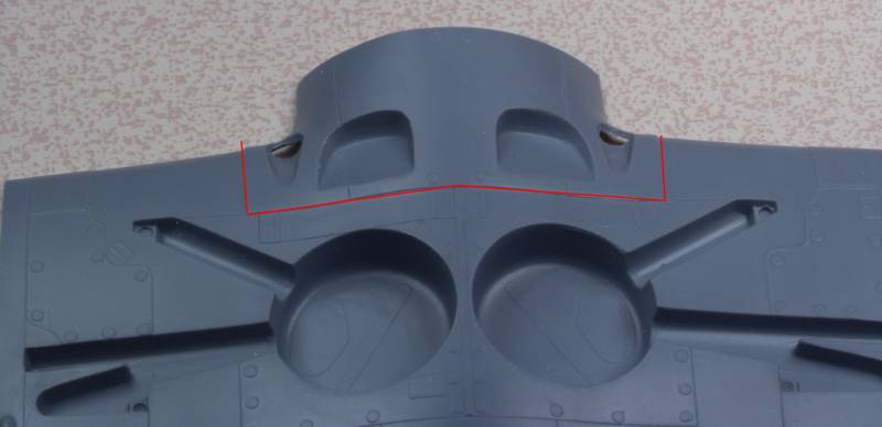
Once the deed was done I was able to see what other sort of grief I was in for getting the rest of it together. I cut off the crankshaft and drilled and tapped the crankcase for a screw I could use to hold the engine to the cowling while test fitting other things. A couple things became readily apparent. Mainly that this set was intended only to be used with all the panels off. If I wanted to get the panels to fit closed up I would need to sacrifice yet more details. The red lines on the photo below show detail that would need to be removed to get the panels to set flush. I thought maybe I could cut recesses for them on the inside of the panels but it would be a crap shoot since the panels are already pretty thin anyway. Not only that but the rear portion of the rocker panels that I had saved when fitting the engine to the cowl would need to go as well.
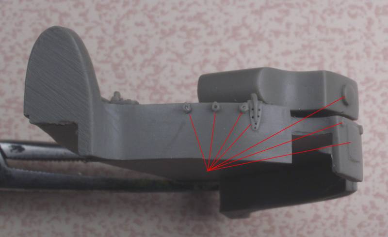
Another area of concern was the part that would replace the lower cowling that was part of the lower wing on the kit. Some of the parts on the castings were very thin and it is thin in places where filling and sanding are likely to need as well as strength when attaching the wings.
After mulling this over for days I finally took a deep breath and said enough is enough. New plan I will attach the parts to the front of the engine that might be seen through the openings in the cowl and use it and the cowl to replace the kit cowl. I may be able to use the exhaust stacks but the rest is going into the left over goody box and I can get on with this build.
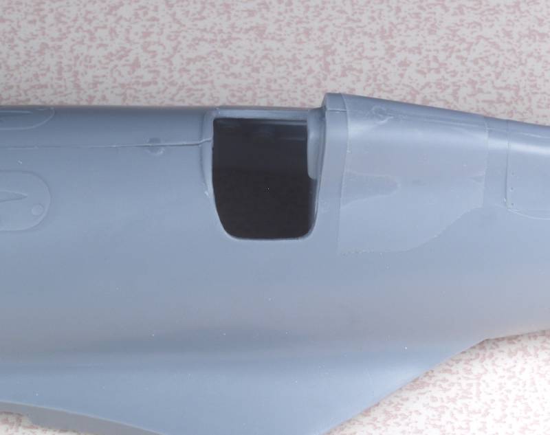
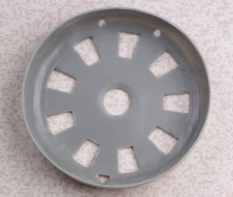
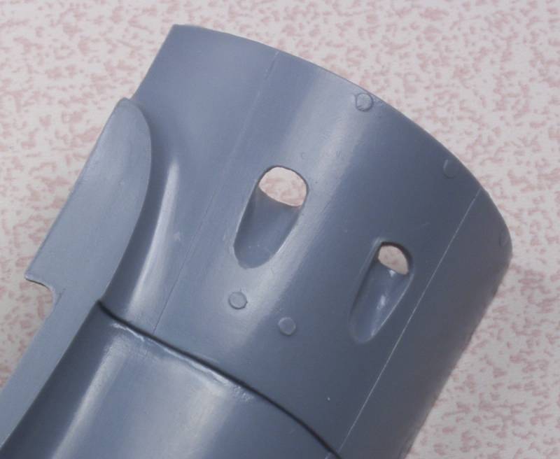
I am going to open up all of the exhaust vent opening in the kit cowl and maybe I can then use the resin exhaust stacks but overall I think going this route will not only save a lot of hair pulling but make for a stronger overall build. Next shot shows one of the openings already enlarged compared to one that has not, I think it will make a big difference in the overall look.
Hopefully next update will show some real progress.
Thanks for looking in!
In reality all I wanted was an engine and a new front cowling. I figured all the other stuff would just be icing on the cake. I really don't like building kits all opened up but I figured I could mount the panels with some double faced tape or sticky tack. Well that ain't gonna happen. I started by mounting the cylinders to the crankcase, no problems there. Before adding anything else I tried fitting the engine into the cowl...no go. Now I'm only too aware that most time Vector engines don't fit where we want them but its most often the result of the kit cowlings being a scale 6" or more thick. In this case Vector made both parts, one would think they would fit. I had no problems fitting the Vector engine into the Vector cowl on the Su-2. My first attempt was to remove as much of the inner cowl as I could. It's down to almost scale thickness and still no go, I could push the cylinders in but they would just deform the cowling.
So it looked like the only option was to sand off the tops of the rocker covers. Since only part of these go into the cowl I figured I would only need to remove the part that did and it was not a big deal cause it was in an area that wouldn't show anyway. More on this later. Disappointing but not a show stopper.
Once the deed was done I was able to see what other sort of grief I was in for getting the rest of it together. I cut off the crankshaft and drilled and tapped the crankcase for a screw I could use to hold the engine to the cowling while test fitting other things. A couple things became readily apparent. Mainly that this set was intended only to be used with all the panels off. If I wanted to get the panels to fit closed up I would need to sacrifice yet more details. The red lines on the photo below show detail that would need to be removed to get the panels to set flush. I thought maybe I could cut recesses for them on the inside of the panels but it would be a crap shoot since the panels are already pretty thin anyway. Not only that but the rear portion of the rocker panels that I had saved when fitting the engine to the cowl would need to go as well.
Another area of concern was the part that would replace the lower cowling that was part of the lower wing on the kit. Some of the parts on the castings were very thin and it is thin in places where filling and sanding are likely to need as well as strength when attaching the wings.
After mulling this over for days I finally took a deep breath and said enough is enough. New plan I will attach the parts to the front of the engine that might be seen through the openings in the cowl and use it and the cowl to replace the kit cowl. I may be able to use the exhaust stacks but the rest is going into the left over goody box and I can get on with this build.
I am going to open up all of the exhaust vent opening in the kit cowl and maybe I can then use the resin exhaust stacks but overall I think going this route will not only save a lot of hair pulling but make for a stronger overall build. Next shot shows one of the openings already enlarged compared to one that has not, I think it will make a big difference in the overall look.
Hopefully next update will show some real progress.
Thanks for looking in!
Similar threads
- Replies
- 11
- Views
- 2K
- Replies
- 52
- Views
- 8K