Adam Baker
Active member
This is a build that I started about 4 1/2 years ago during the Helo GB on ARC in 2008. I made some decent progress, but before making too much headway, I moved, and since I had a much smaller work area, I never pulled the kit back out. About 6 weeks ago, my wife & I moved into a place of our own and I finally have a larger work area, so I've pulled it back out and started working on it again.
I started w/ working on the main rotor, lots of parts in this assembly. I decided that instead of it being in the in flight position, I went w/ showing it in the stowed position.
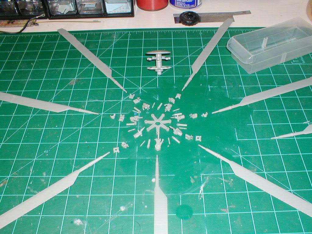
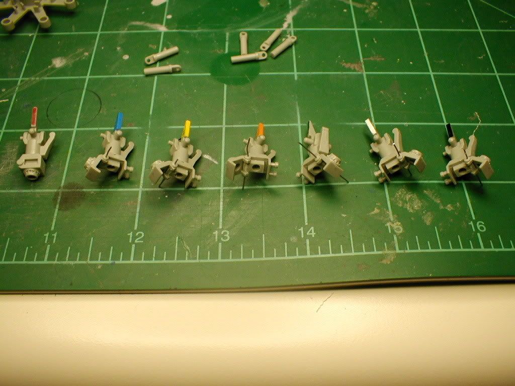
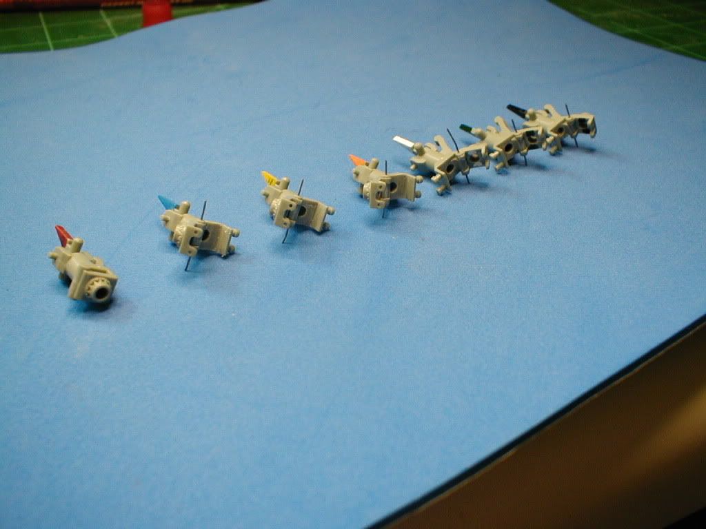
After laying everything out, I started working on the bases of each rotor. Each rotor blade is at a slightly different angle when stowed, so its important to keep each separate. On the real thing, each blade has a color associated w/ it, and I followed the same scheme, so I could keep the parts straight. Also, to strengthen the hinge joint of each blade, which I felt could be a very weak location, I drilled each out w/ a #78 drill bit, and then put a piece of wire in the joint, so I shouldn't have to worry at all about it breaking.
Because the hinge components are so visible, I decided to start working on detailing them. The part that the rotor blade attaches to, has a notch in the center, and 2 holes for the pins that secure the hinge joint for flight. Was very concerned about this, but it turned out to be a lot easier to pull off than I had expected it to be. Probably less than 5 minutes per part. Used a small modeling file to get the notch in the center, and a .028" drill bit was used to drill the holes.
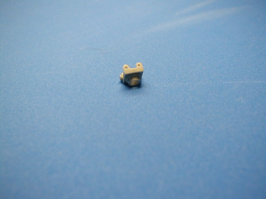
Once I had that done, I started on the base portion of the blade mount. There's a large block on each hinge joint, to support the rotor blade when in the flight position. I decided to remove this block on mine, so that I could try to scratch build the hinge mechanism.
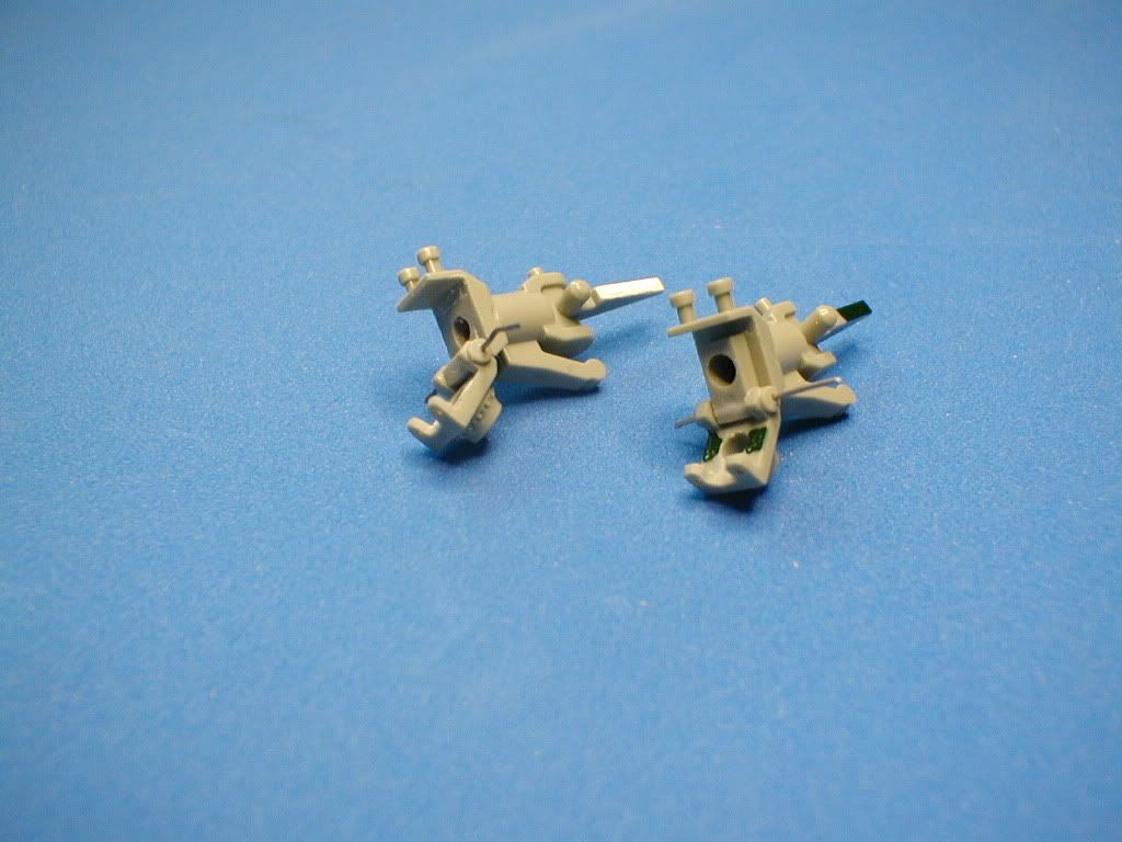
This same thing was done to all 6 hinge joints.
Once satisfied w/ the rotor head, I moved on to the fuselage. After seeing a few other builds, I decided to simulate the rivets that are so prominent on the fuselage. Using a 21 TPI pounce wheel, and plastic Dymo label tape, I riveted all of the fuselage components.
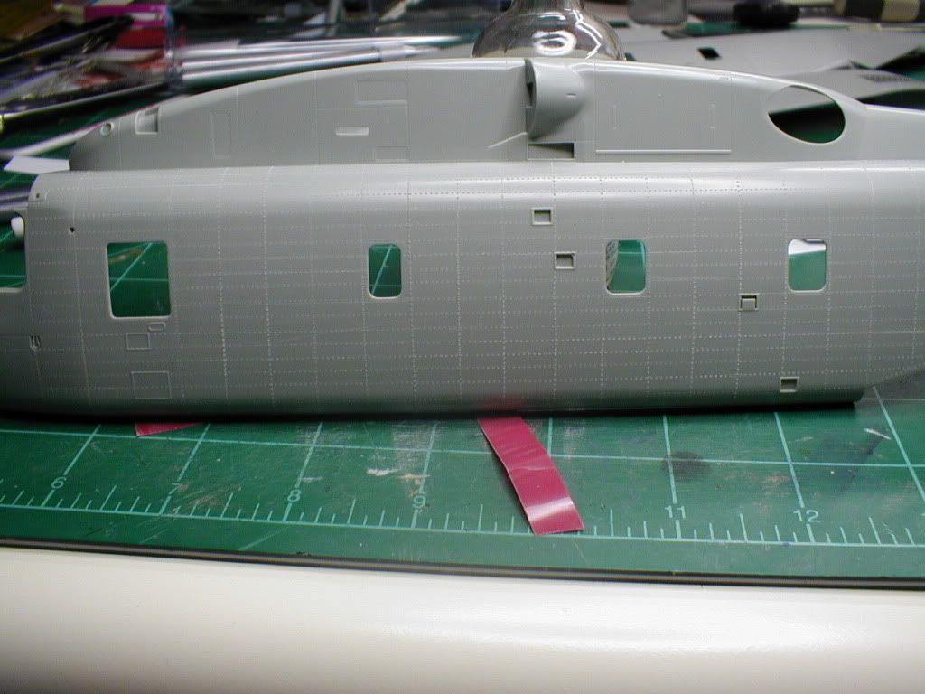
Something I've thought about, since riveting the fuselage halves, is that Archer makes some very nice water transfer rivet decals, that I'm considering trying out on this build, to see how effectively it could be used to represent the rivets, instead of using recessed holes like I have now. Only problem is the expense, it'll take a lot of those rivets to do the whole fuselage, so I'm not sure if I'll do it, but I've got plenty of time to decide.
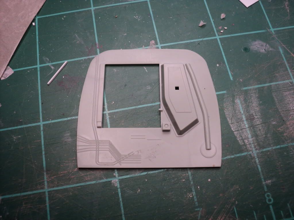
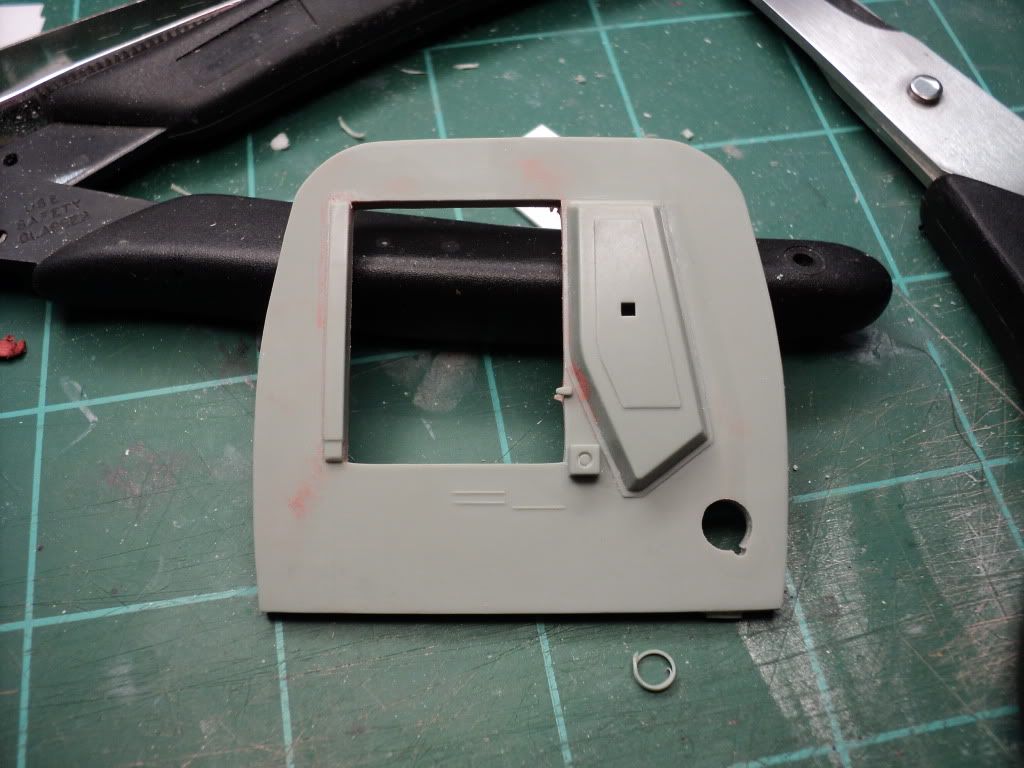
When I started on this build, I'd had several ideas of things to do to kinda take the build to the next level, and really push my abilities to do a lot of things. Doing that, I decided to open pretty much every compartment visible on the exterior of the helo. This includes 2 engines, the main rotor transmission, oil cooler, and all 3 electronics bays in the nose, and the APU compartment above the cockpit.
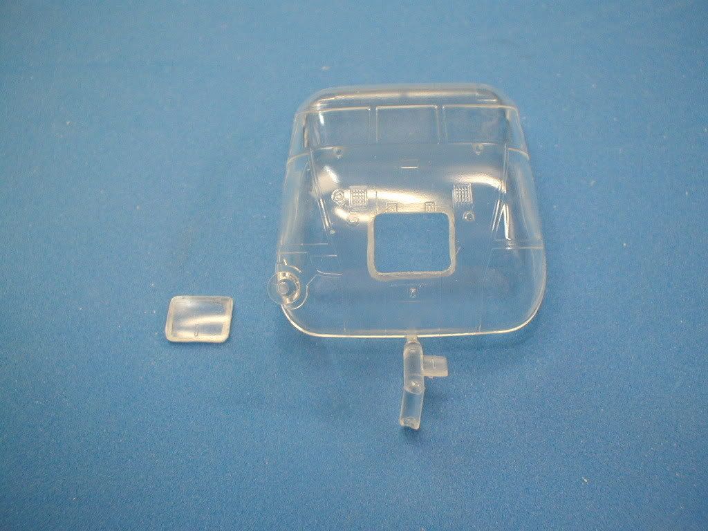
To do this, I began opening the various panels, using a sewing needle in my pin vise. I also used a grinding bit in my Dremel tool to thin the plastic from behind. Overall this process went quite wheel, including cutting the door loose in the clear plastic nose.
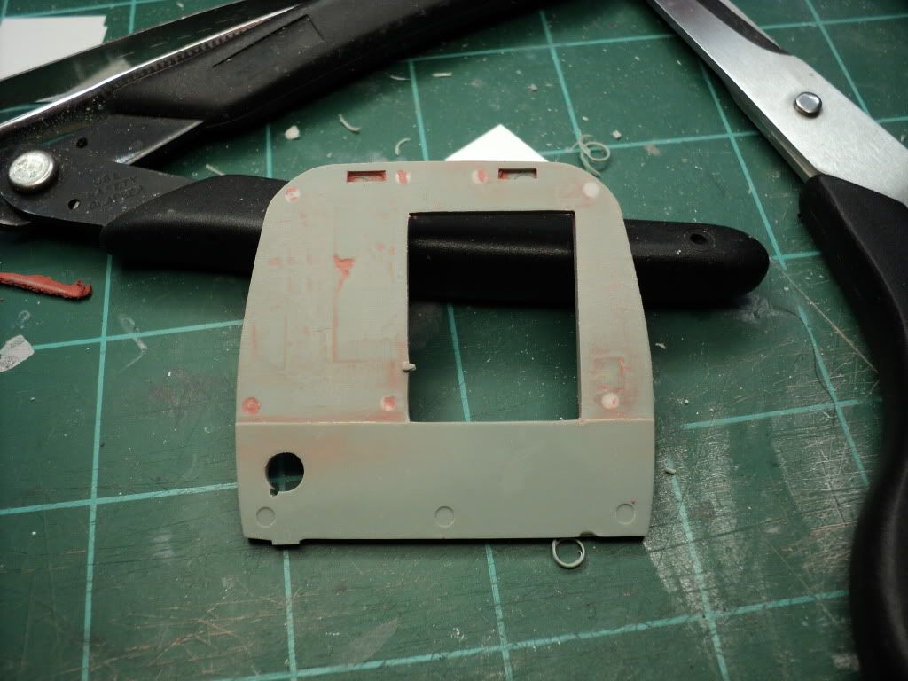
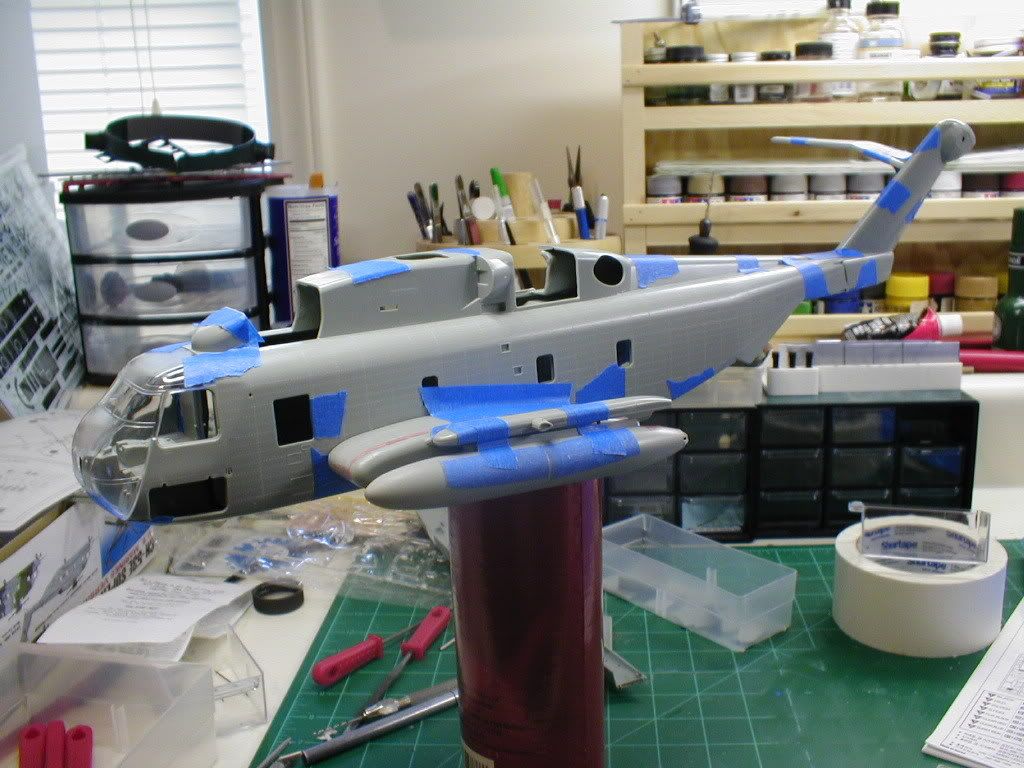
Here you can see a dry fit test I did, showing most of the compartments that I opened.
And that was pretty much where I wrapped things up 4 years ago.
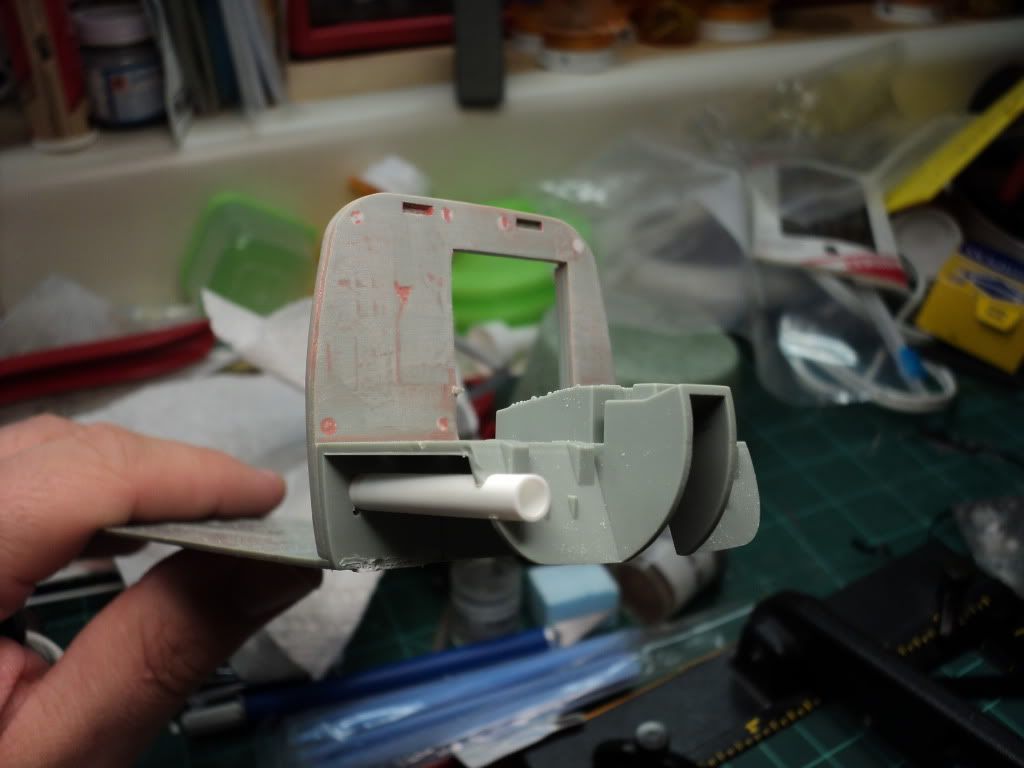
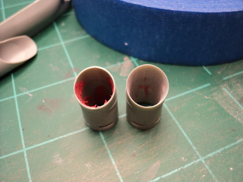
When I pulled the build back out, I started working on the engine exhausts. B/c of how the plastic is molded, the exhaust is obviously well beyond scale thickness, so I corrected this issue, and it looks much better.
The unmodified exhaust is on the left and the completed exhaust is on the right. I'm very happy w/ how this turned out on all 3 exhausts, it looks much better than leaving it the stock thickness.
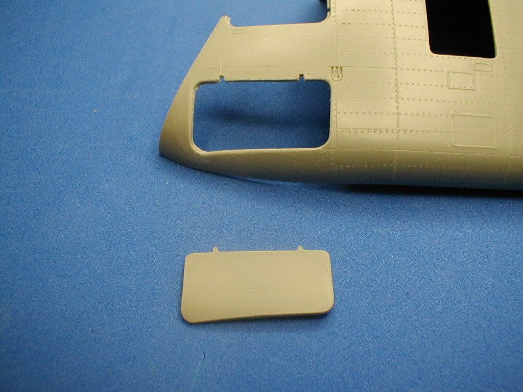
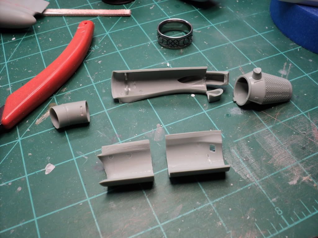
Once I was done w/ the exhaust, I started working on the housing for the engine on the starboard side of the fuselage. I used the same method to cut open the engine that I used for all the other compartments.
After a lot of work, this is what the starboard engine compartment looks. For the 2 access doors, I'm trying to decide what I want to do, to achieve thinner doors. I thought about trying to smash mold, but I don't know that I can get it to shape to the compound curves, and unfortunately I don't have access to a vacuform machine, which is probably what it would take to form correctly. I've thought about sanding them down thinner, or just leaving them alone. What ever I do, I still have to add the ribbing on the insides of each door, and work on the inside of the housing as well.
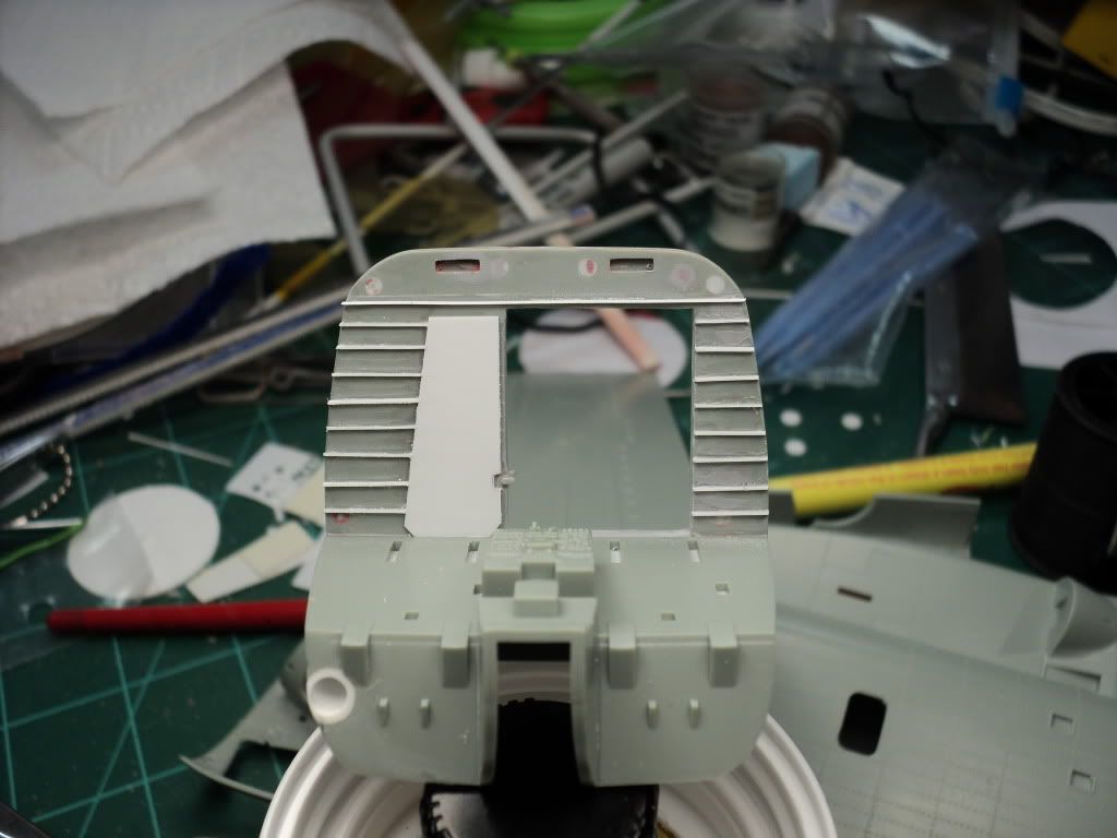
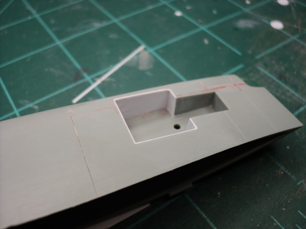
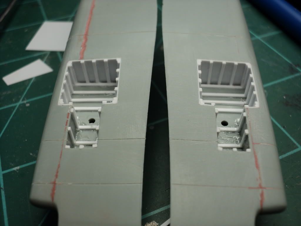
The last thing I've worked on are the main landing gear bays. The stock bays have absolutely no detail on them, so I decided to add ribbing similar to what is molded on the nose gear bay.
Started by putting in .010" styrene sheet on the sides to cover the join seams, which I tried filling w/ putty and just didn't like the look. I then took a sheet of .020" styrene and cut a bunch of strips about .050" wide, and then started gluing them in. When finished, I was pretty happy w/ the look. And then I got pictures of the underside, and unfortunately it looks like I probably couldn't be farther away from accurate than if I'd just left it alone. However, once complete and the model is mounted on a base, you wont be able to see any of this area anyway, so I'm just going to live w/ what I've got, and move on.
This evening I just started working on the interior. I've decided to attempt scratch building the interior. The kit comes w/ blankets molded on the interior walls. I found out that these blankets are usually removed fairly quickly, leaving the interior ribbing very visible. Since I'm going for broke on the exterior, I figured I might as well go for it on the interior as well.
I started w/ working on the main rotor, lots of parts in this assembly. I decided that instead of it being in the in flight position, I went w/ showing it in the stowed position.
After laying everything out, I started working on the bases of each rotor. Each rotor blade is at a slightly different angle when stowed, so its important to keep each separate. On the real thing, each blade has a color associated w/ it, and I followed the same scheme, so I could keep the parts straight. Also, to strengthen the hinge joint of each blade, which I felt could be a very weak location, I drilled each out w/ a #78 drill bit, and then put a piece of wire in the joint, so I shouldn't have to worry at all about it breaking.
Because the hinge components are so visible, I decided to start working on detailing them. The part that the rotor blade attaches to, has a notch in the center, and 2 holes for the pins that secure the hinge joint for flight. Was very concerned about this, but it turned out to be a lot easier to pull off than I had expected it to be. Probably less than 5 minutes per part. Used a small modeling file to get the notch in the center, and a .028" drill bit was used to drill the holes.
Once I had that done, I started on the base portion of the blade mount. There's a large block on each hinge joint, to support the rotor blade when in the flight position. I decided to remove this block on mine, so that I could try to scratch build the hinge mechanism.
This same thing was done to all 6 hinge joints.
Once satisfied w/ the rotor head, I moved on to the fuselage. After seeing a few other builds, I decided to simulate the rivets that are so prominent on the fuselage. Using a 21 TPI pounce wheel, and plastic Dymo label tape, I riveted all of the fuselage components.
Something I've thought about, since riveting the fuselage halves, is that Archer makes some very nice water transfer rivet decals, that I'm considering trying out on this build, to see how effectively it could be used to represent the rivets, instead of using recessed holes like I have now. Only problem is the expense, it'll take a lot of those rivets to do the whole fuselage, so I'm not sure if I'll do it, but I've got plenty of time to decide.
When I started on this build, I'd had several ideas of things to do to kinda take the build to the next level, and really push my abilities to do a lot of things. Doing that, I decided to open pretty much every compartment visible on the exterior of the helo. This includes 2 engines, the main rotor transmission, oil cooler, and all 3 electronics bays in the nose, and the APU compartment above the cockpit.
To do this, I began opening the various panels, using a sewing needle in my pin vise. I also used a grinding bit in my Dremel tool to thin the plastic from behind. Overall this process went quite wheel, including cutting the door loose in the clear plastic nose.
Here you can see a dry fit test I did, showing most of the compartments that I opened.
And that was pretty much where I wrapped things up 4 years ago.
When I pulled the build back out, I started working on the engine exhausts. B/c of how the plastic is molded, the exhaust is obviously well beyond scale thickness, so I corrected this issue, and it looks much better.
The unmodified exhaust is on the left and the completed exhaust is on the right. I'm very happy w/ how this turned out on all 3 exhausts, it looks much better than leaving it the stock thickness.
Once I was done w/ the exhaust, I started working on the housing for the engine on the starboard side of the fuselage. I used the same method to cut open the engine that I used for all the other compartments.
After a lot of work, this is what the starboard engine compartment looks. For the 2 access doors, I'm trying to decide what I want to do, to achieve thinner doors. I thought about trying to smash mold, but I don't know that I can get it to shape to the compound curves, and unfortunately I don't have access to a vacuform machine, which is probably what it would take to form correctly. I've thought about sanding them down thinner, or just leaving them alone. What ever I do, I still have to add the ribbing on the insides of each door, and work on the inside of the housing as well.
The last thing I've worked on are the main landing gear bays. The stock bays have absolutely no detail on them, so I decided to add ribbing similar to what is molded on the nose gear bay.
Started by putting in .010" styrene sheet on the sides to cover the join seams, which I tried filling w/ putty and just didn't like the look. I then took a sheet of .020" styrene and cut a bunch of strips about .050" wide, and then started gluing them in. When finished, I was pretty happy w/ the look. And then I got pictures of the underside, and unfortunately it looks like I probably couldn't be farther away from accurate than if I'd just left it alone. However, once complete and the model is mounted on a base, you wont be able to see any of this area anyway, so I'm just going to live w/ what I've got, and move on.
This evening I just started working on the interior. I've decided to attempt scratch building the interior. The kit comes w/ blankets molded on the interior walls. I found out that these blankets are usually removed fairly quickly, leaving the interior ribbing very visible. Since I'm going for broke on the exterior, I figured I might as well go for it on the interior as well.
")