• Modelers Alliance has updated the forum software on our website. We have migrated all post, content and user accounts but we could not migrate the passwords.
    This requires that you manually reset your password.
    Please click here, http://modelersalliance.org/forums/login to go to logon page and use the "Forgot your Password" option.

1/48 Hasegawa F-15C Aggressor

Skinny_Mike

Well-known member
Hi everyone! I've been way behind on my campaign builds lately, but that because of another project I have going on the bench right now. I started this F-15 as part of the Bad Boys Group Build over on ARC, and unfortunately I didn't get it done in time. But I am still working on it and thought I would share my progress here with my friends at MA!

Let me catch you all up... (I'll break this up into the 6 posts I've made so far over at ARC)

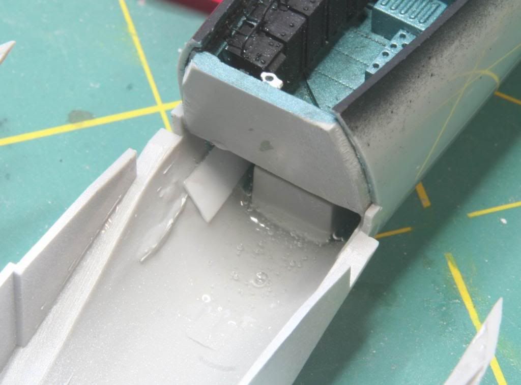
My contribution will be a 1/48th scale Hasegawa F-15C from the 65th Aggressor Squadron. I'll be adding a lot of aftermarket to this on as well. Here is what I have...

Post11_zpsece029f7.jpg


And the list:
Hasegawa F-15C
Afterburner Decals
Aires F-15C Late Cockpit
Aires F-15C Late Exhaust Nozzles
Quickboost Seat
Wolfpack F-15C/D Aggressor Update Set
Royale Resin F-15 Wheels
Hypersonic Models F-15 Jet Fuel Starter Exhaust

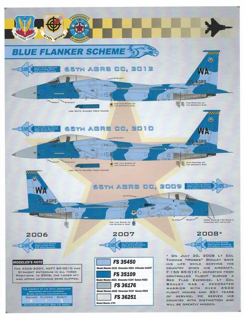
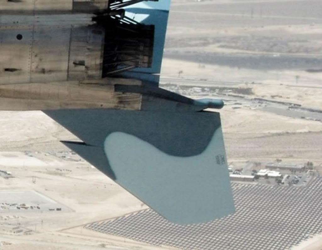
Plan is to do the Blue Flanker Scheme, likely this jet:

Post12_zpsfddebe5f.jpg


So there it is. Probably won't get started until next weekend, lots of other projects on the bench right this minute.
 
Hey everybody! Finally got started on my Eagle, but it looks like I am way behind everyone else in the group build! :P/>/>

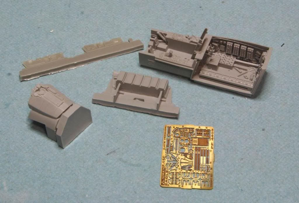
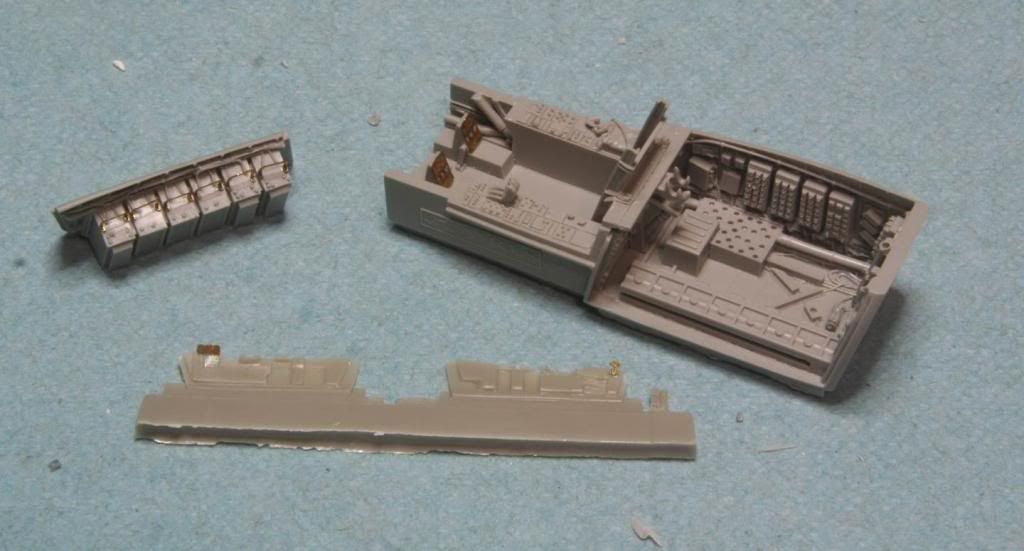
Work started with the cockpit. I am using the Aires F-15C Late cockpit for this build so the first step was a soak in some dish detergent for all the resin parts. Here are the basic parts laid out after their bath.

Post21_zpsfbe34ef7.jpg


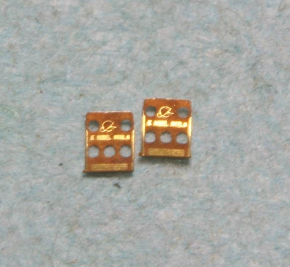
Checkout this detail on the rudder pedals! Is that the Boeing logo? Probably should be the McDonald Douglas Logo, but who cares – still a pretty cool little detail that no one will ever see!

Post22_zpsa37ba3c2.jpg


I next put all the sub-assemblies together prior to painting the pit.

Post23_zps4a0185a6.jpg


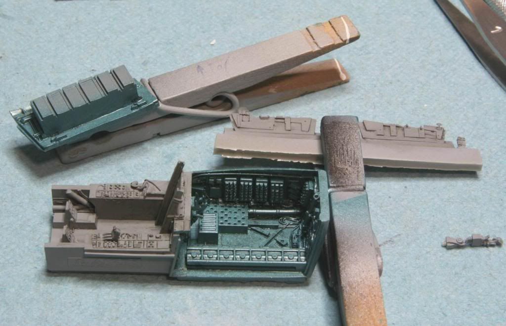
And then I painted the whole thing with Model Master Dark Gull Gray. While the paint was drying I started a search for reference photos of the cockpit for my detail painting. This is when I discovered my first mistake! The avionics bay behind the cockpit isn’t gray at all! Oops! We’ll easily fixed. Since I am building an aircraft with FY 79 serial number, I painted the bay in the Model Master Interior Metallic Blue. I had tried this color many moons ago on a Zero. It was wrong for that, but perfect for the F-15! After the paint all dried I gave it a coat of future and then wash with MIG dark wash to dirty it all up a bit, followed by a MM Flat coat on the cockpit and a MM semi-gloss coat over the avionics bay.

Post24_zps0ba5c590.jpg


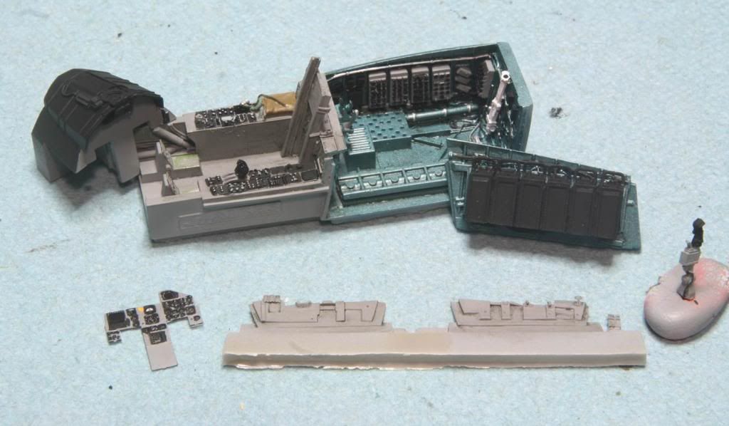
After that all cured overnight I did all the detail painting. I used a variety of colors to get the look I was going for. Most were acrylics.

Post25_zps71502a4a.jpg


Once the detail painting was finished I assembled all the pieces.

Post26_zps6a6d54f2.jpg


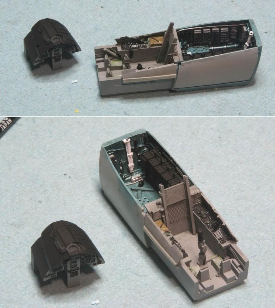
Overall I am quite pleased with the result. Next step is to fit all these pieces together. I was just playing around a little bit and it looks like it might all go together with a minimum of fuss. Of course, I haven’t tried the nose gear well yet. :whistle:/>/>

Post27_zps8cc5966b.jpg


Thanks for looking! And as always, critiques are welcome!
Mike
 
Hi everyone! I’ve been working hard on my F-15, but its still at that point where there isn’t much to show. Here is a short update.

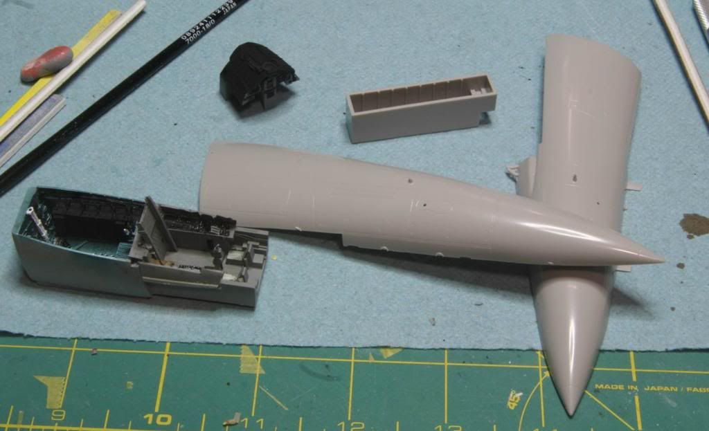
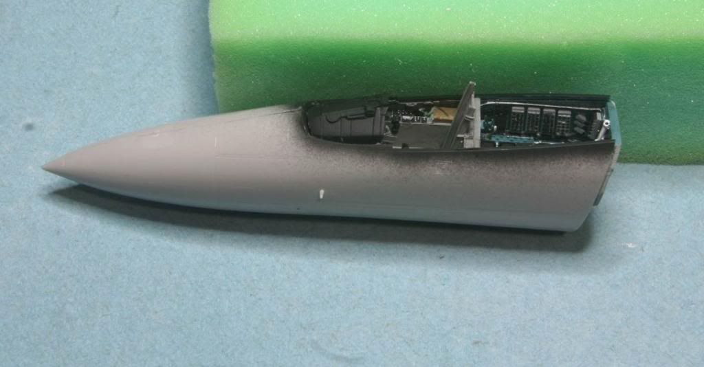
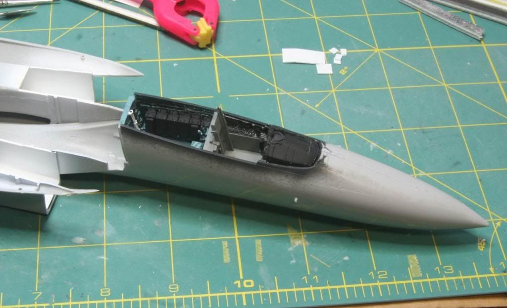
I’ve finished the front of the aircraft. After I completed the cockpit, I sanded out the minimal interior details and removed the kits glare shield, then I painted the interior of the nose in the interior blue and interior black, plus the cockpit sill was painted in interior black. I did some dry fitting and sanded out the areas I thought might have an interference, but surprisingly there weren’t very many. I then assembled the two forward fuselage parts and added some weight to the nose. For this I dumped some lead fishing weights in the nose while it was standing on end, and then poured in some thin CA glue until it covered the weights. I left the nose sitting upright overnight to let the CA glue dry. Then I installed the kit nose landing gear bay. There is almost no detail in the bay and I considered replacing it with an Aires one, but it seemed like a waste since Eagles generally have most of their gear doors closed when they are on the ground anyway, so no detail will really be seen. After a little research, I’m not even really sure anyone has an aftermarket landing gear bay set for this kit, oh well really don’t need it. Next I moved on to fitting the pit. I had to sand the residual pour block off the bottom of the pit to make it fit with the landing gear bay. Once that was sanded down the cockpit slid right into place.

Post31_zps248fa33c.jpg


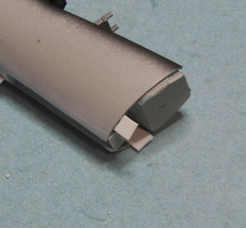
If I was to do this again, I think I would have installed the nose gear bay after the cockpit was in place, just so I could reach the front of the cockpit to help align and secure it in place. Would have been a better assembly order. After doing a little research on this kit, it seems a lot of people have had problems with the joint between the front and back fuselage. With a resin pit and weight in the nose, I agree that the butt joint that Hase planned will need some help. So I added a couple of pieced of sheet plastic to the front half, to help give a little more bonding surface and I plan to use some 5 minute Epoxy to get a good strong joint.

Post32_zpse2673056.jpg


After some dry fitting, I found that the fit between the front fuselage and the lower portion of the aft fuselage fits perfectly. I’ve heard that to be a problem with this kit, but its been suggested that the Aires pit helps straighten that out. All I know is mine fits great.
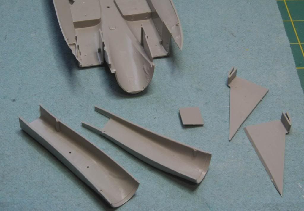
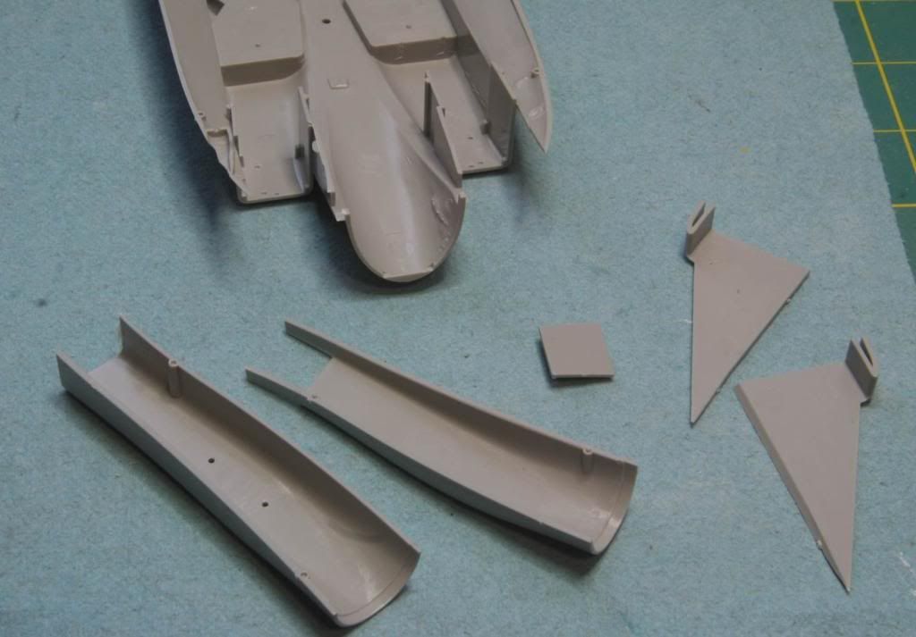
Next step is the intakes. It seems they are going to be a challenge to get seem-less. I try to buy aftermarket intakes where ever I can (I’m lazy that way – I admit it! :whistle:/> ) but the only ones I know about are the Two Mike’s ones and it seems that Two Mike’s is now out of business. Oh well. I guess will give the kit parts a go! Here are the parts that make up one intake, not counting the ramp and the upper fuselage half!

Post33_zps205302f4.jpg


My usual weapon of choice is the latex paint pour method, but that won’t work here. Too many parts. Time to go old school. Putty and sanding. I think I have a strategy. I’m going to try it on one of the intakes and see how it works out. Then I’ll regroup if I have to for the other intake. :pray:/>

That’s where I am today. I am really enjoying this group build. A lot of great work on some colorful airplanes, its fun to watch. Oh yeah – Phantom – slow down! You’re making the rest of us look bad! :P/>

Thanks for looking! See you next time.
Mike
 
Well its been quite a while since I had made any progress on this thing. I’ve had a few other projects on the bench and I really lost my motivation with those intakes. I don’t think I’ll quite have this finished by the 1 July deadline, but I’ll give it a go.

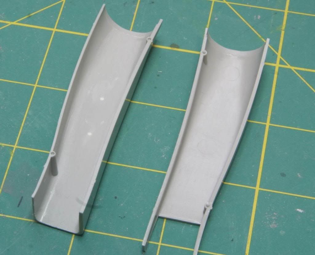
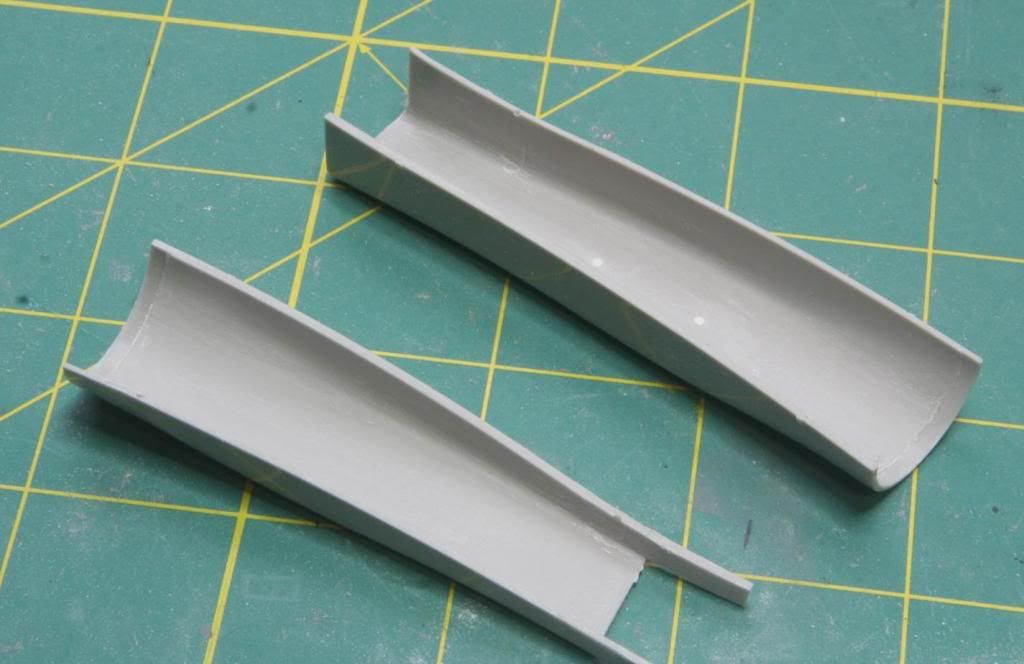
Alright onto the intakes! Each intake is made up of 5 parts plus part of the lower fuselage tub. There is also the intake ramp and the top half of the fuselage.

Post33_zps390da8fd.jpg


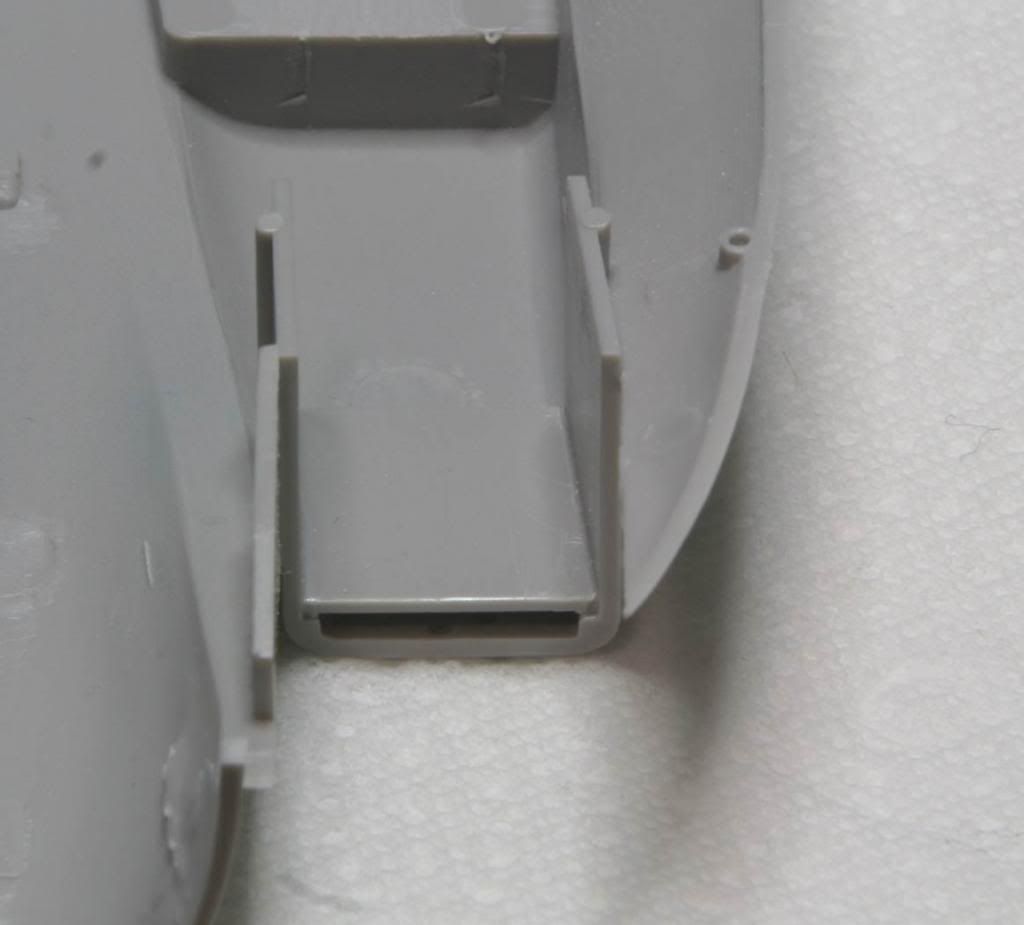
I started by cleaning up the mounting through holes in the bottom half of the intake trunk.

Post41_zpsb4851872.jpg


Then I sanded down the mounting pins for the top and bottom halves.

Post42_zpsae4f0b43.jpg


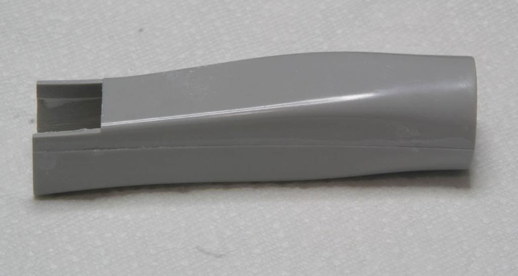
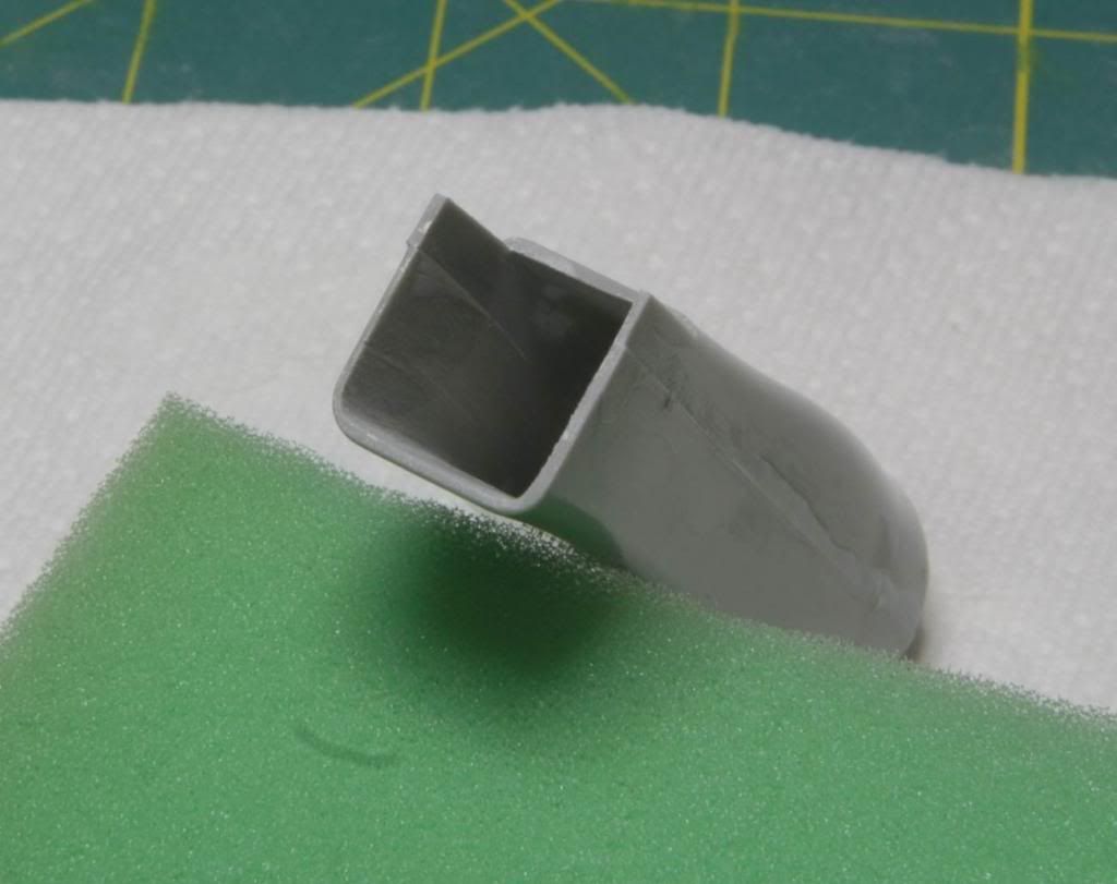
Once the inside was cleaned up, I mated the intake halves and filled the seams with 2 part milliput. This sanded much smoother and filled the seams on the first try! This was my first time trying this technique and I was quite pleased.

Post43_zps254849e5.jpg


Post44_zps522bd42f.jpg


Next the small raised portion was added to the lower fuselage tub.

Post45_zps6f6a1bff.jpg


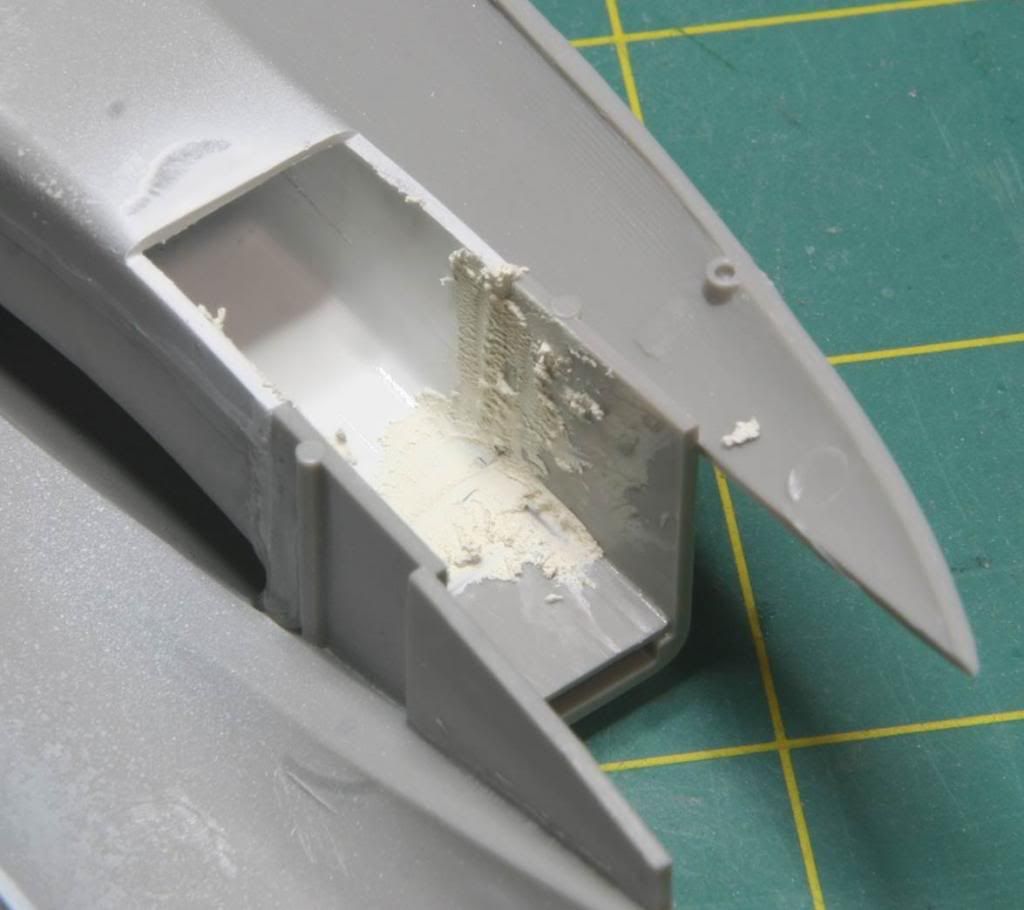
The intake trunk was airbrushed with Tamiya Gloss White and installed in the fuselage. More Milliput was added to fill the gaps and smooth out the front of the intake.

Post46_zps512cf6f5.jpg


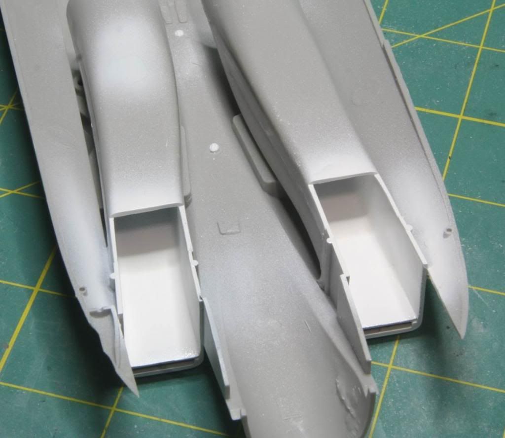
Once it was smoothed out the whole thing was again painted in Tamiya Gloss White. Both intakes were completed at this point.

Post47_zps8693b910.jpg


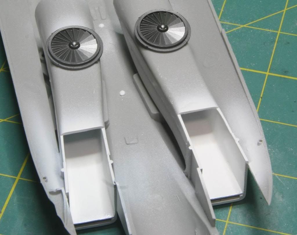
The engine faces were painted in Alclad Steel and installed, completing the main intake trunks.

Post48_zpsd8b5604e.jpg


I know this doesn’t look like a lot of work, but I basically spent about a week on each trunk. I’m glad I am past this part. Next I am going to depart from the instructions at this point and add the forward intakes after I have the fuselage together. I think that will allow me to get everything nice and straight.

Post49_zpsfd1f72c2.jpg


The bad news is, I’m probably not going to finish on time, but the good news is that I am moving along again! See you all soon.

Thanks for looking
Mike
 
Hi guys! Back with another update. This one is a little long...

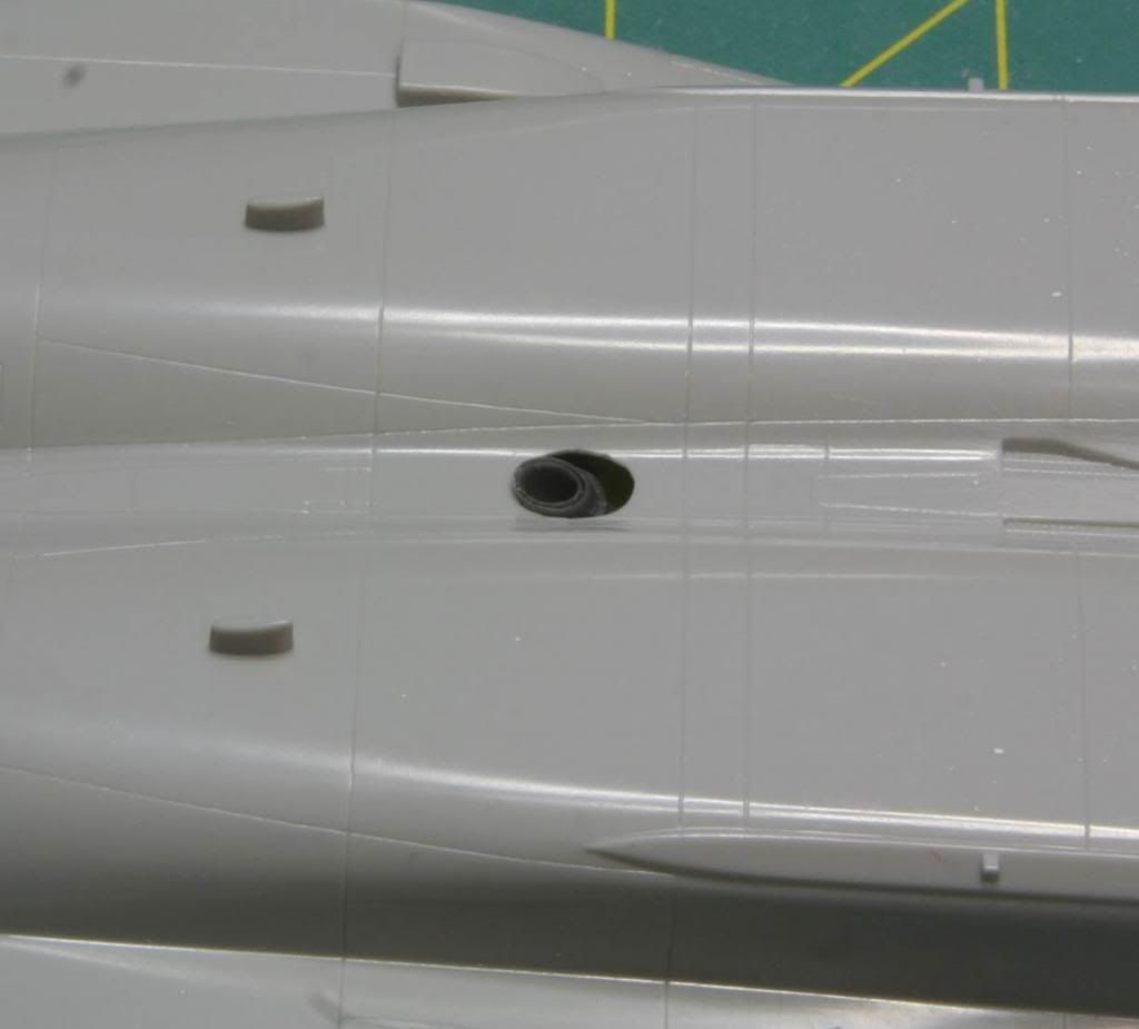
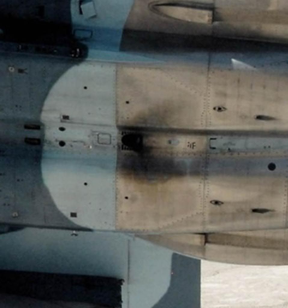
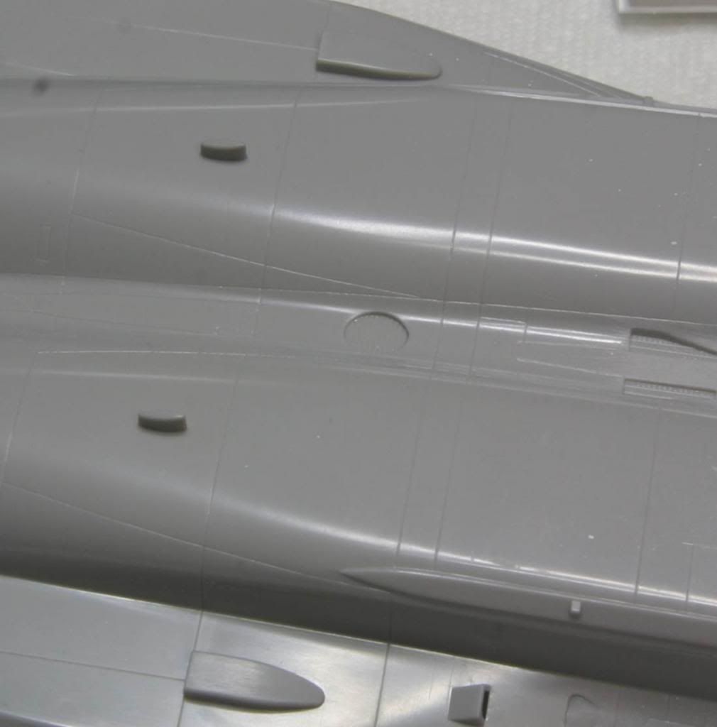
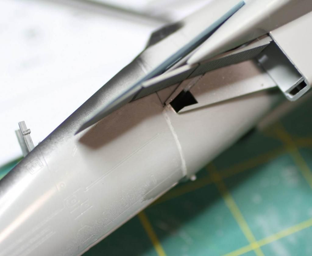
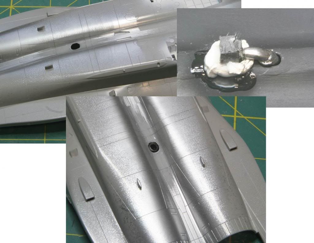
Next step after the intakes was to update the Jet Fuel Started Exhaust. F-15s were updated with a new exhaust and the Hasegawa kit sit has the old screened over hole. The exhaust sits between the engines and is located on the bottom of the aircraft, just aft of where the natural titanium starts. Here is what the exhaust looks like today.

Post50_zpsc2113321.jpg


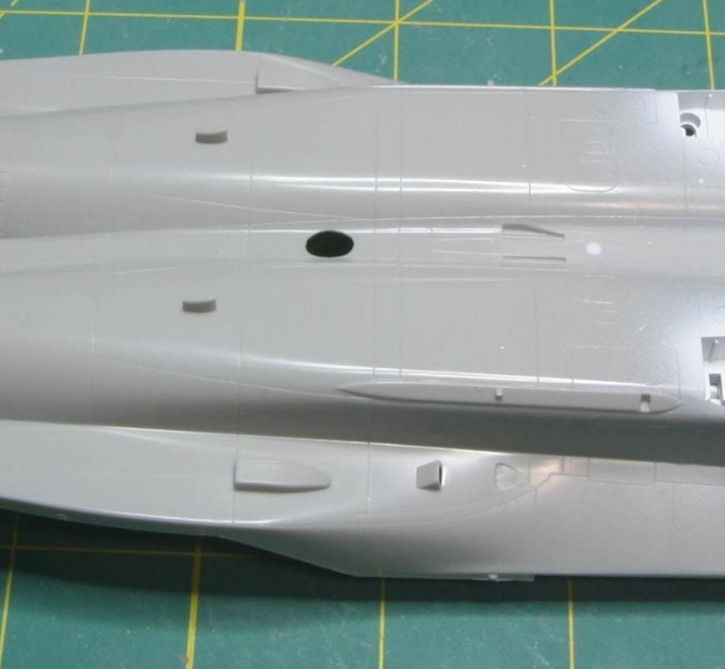
And here is what it looks like on the kit

Post52_zps0fb057f5.jpg


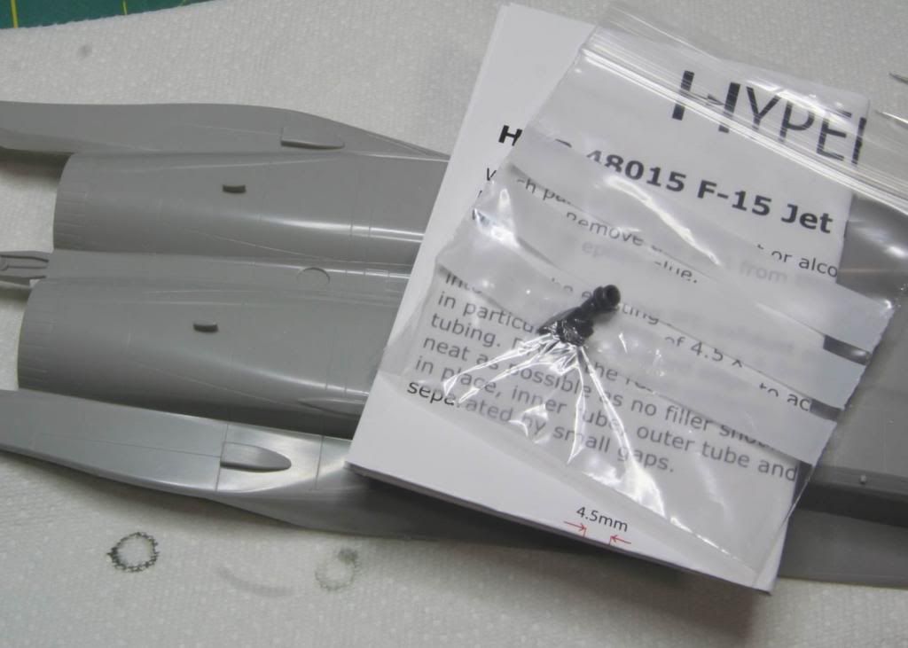
I used the Hypersonic Models resin part for the upgrade.

Post51_zps882e0c0e.jpg


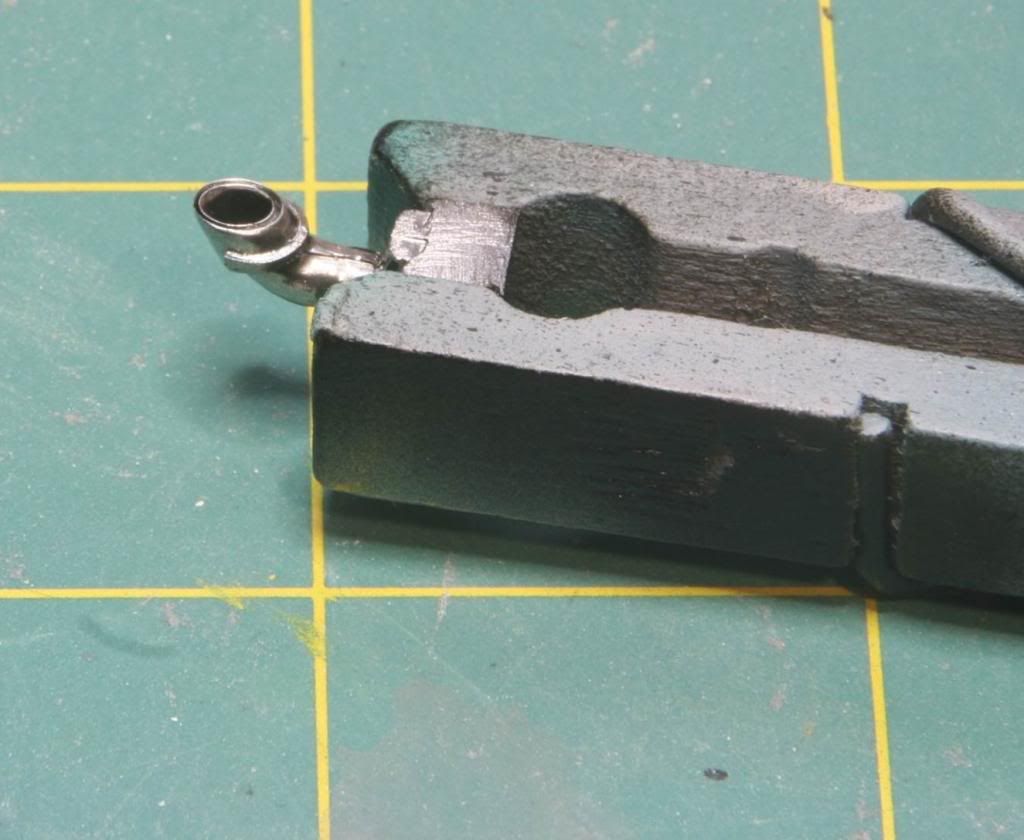
I painted the part in Alclad Stainless Steel. I wanted that dark metallic look.

Post535_zpsa5387d32.jpg


I sanded out the kit exhaust from the inside and then thinned out the plastic on the inside.

Post53_zpsc0785373.jpg


Then a dry fit revealed a bit of a problem…

Post54_zps6ce85253.jpg


The hole on the kit was too big! Turns out that the hole, as descried in the hypersonic instructions (probably should have read those!) is smaller than the old exhaust on the kit. :bandhead2:/>/> So I had to fix it. I used some plastic card, drill out the appropriate sized hole and then shaped the outside to fit within the hole I had made in the bottom of the fuselage. I used some Tamiya Cement to get a good bond then used some Miliput to clean up the seam. After a coat of Tamiya Silver Leaf to check for seams, I added some more putty and cleaned it up some more and polished out the scratches. Once the hole was finished I installed the JFS. To do this I used a dab of putty and I continuously adjusted the installation until the putty had solidifies enough and the exhaust was in the right spot/orientation. I let the putty harden for a few hours and then encased the whole thing in CA glue so lock it all in. I didn’t bother removing the casting block as it was perfect for using for installation.
Post55_zpsa3984218.jpg


I think it turned out pretty well in the end.

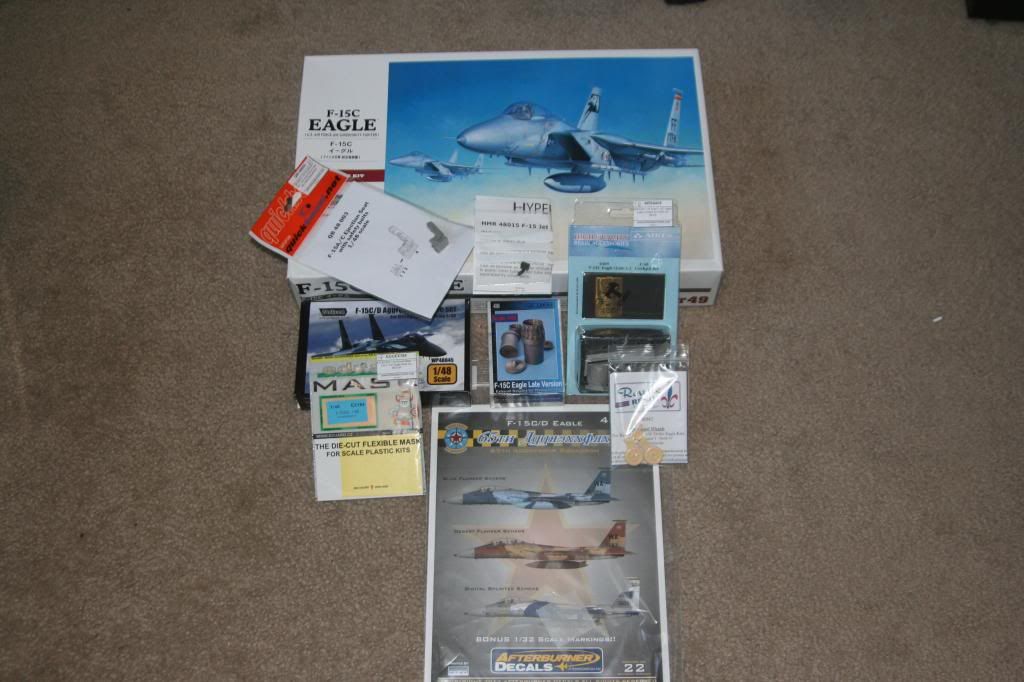
Next step was to mate the forward and aft fuselage. With the weight in the nose and the this being a simple butt joint, I wanted to strengthen the joint a little bit. My first step was to attach the front fuselage to the lower half of the rear fuselage. I used thick CA glue for the join. After about and hour I brushed on some Tamiya cement (The one with the orange cap) along the join on the inside and along the plastic tabs I had installed. I also added some more thick CA glue on the inside of the NLG well to fill the seam. I let the whole thing sit overnight.

Post56_zps3d2ddbb5.jpg


The next step was to strengthen the joint a little more. For this I used some 5 minute epoxy. I mixed it up and basically poured it in around the inside of the fuselage all around the sides and rear of the nose landing gear well and all over the joint. Then I set it aside to set.

Post57_zpsfd7d0d02.jpg


Joint is really strong now. I’m debating replacing the landing gear with metal ones now because of all the weight in the nose, but I’m not 100% on it yet.
Well the next step is to attach the top and the bottom halves of the fuselage. I started looking at the Wolfpack F-15 Aggressor Update set at this point as well. The first thing to do is add is the updated tail antenna and remove the arrestor hook housings.

Here is a shot of the antenna.

Post58_zps64cfae29.jpg


And here is the upper fuselage half with the Wolfpack replacement. I’ve already removed the tail hook housing between the engines.

Post59_zpsaaa934b9.jpg


I removed the unnecessary plastic from the fuselage halves and then mated the top and bottom halves. I’ll add the resin piece after I have the halves together.

Post510_zpsd2e810da.jpg


The halves were put together. The seams are terrible and need of work. There a some substantial seam aft of the wings. But its nothing that some putty won’t fix.

Post511_zpsf25292ee.jpg


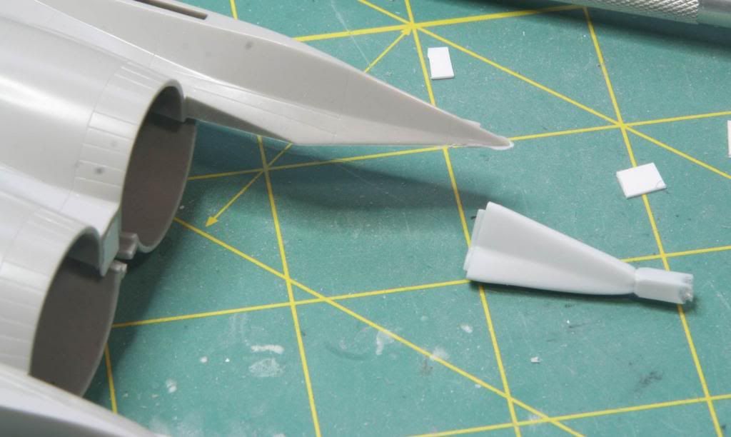
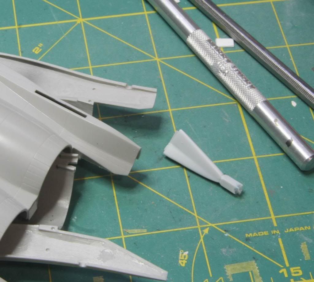
Well that’s about where we are. The next step is to deal with some of the other fit problems on this kit. The first is the remaining parts of the intake. Yikes – not sure how these could be off by so much!

Post512_zpsb92d2550.jpg


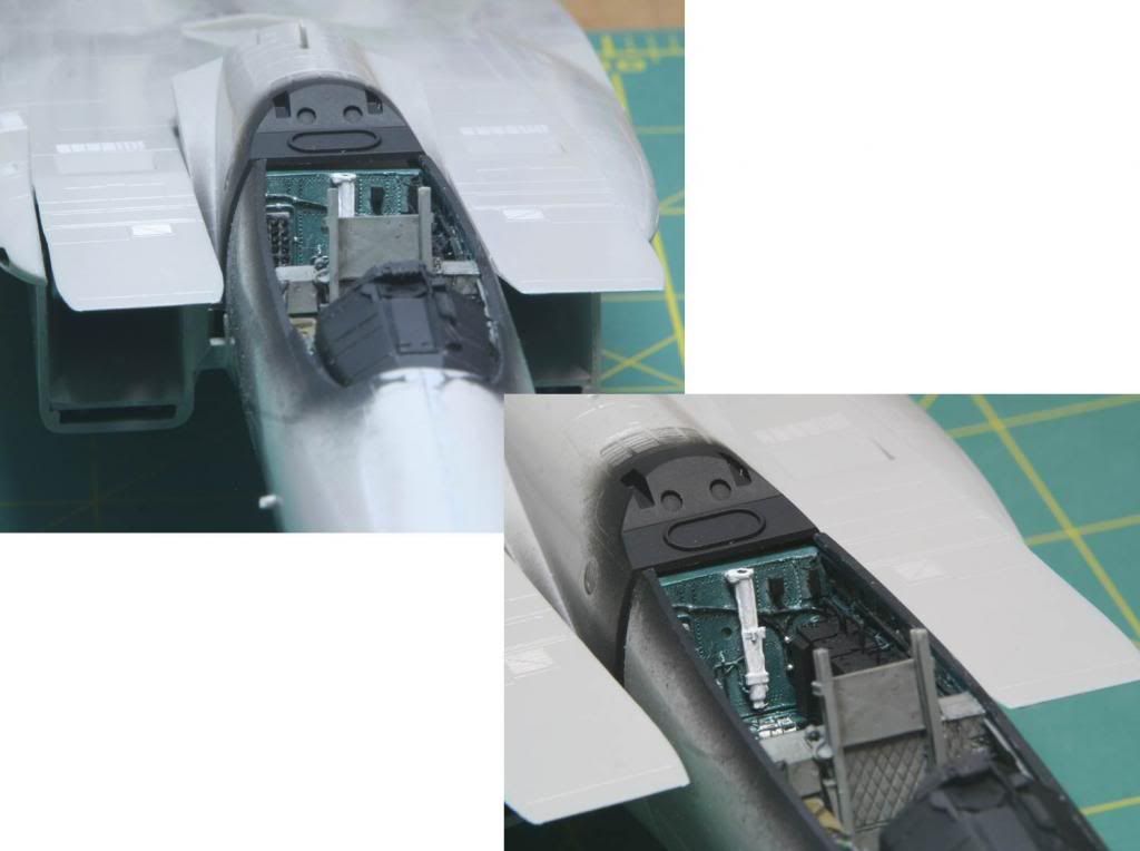
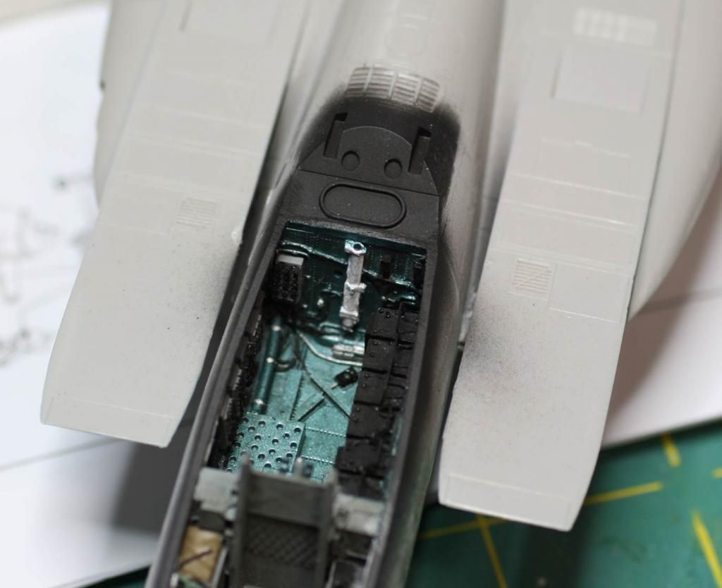
And this gap where the turtle deck meets the cockpit. I’m pretty sure this is because I didn’t get the Aires pit as snug as I should have at the back when I installed it.

Post513_zpseacd8b0b.jpg


Thanks everyone for checking out the build!
Mike
 
And this is where I am currently at...

Picking up where I left off, we are dealing with the fit problems. First up was the gap behind the cockpit. I installed the turtle deck and then to close up the gap I added some plastic strip that was the same thickness as the gap and sanded it to shape. Then I brush painted the interior blue green and finally sprayed interior black. It’s not perfect but will be mostly hidden by the canopy.

Post61_zps5a438198.jpg


Next up was the seam where the forward and aft fuselages are joined. I used some squadron white putty along this seam and wet sanded it.

Post62_zpsbccc4a16.jpg


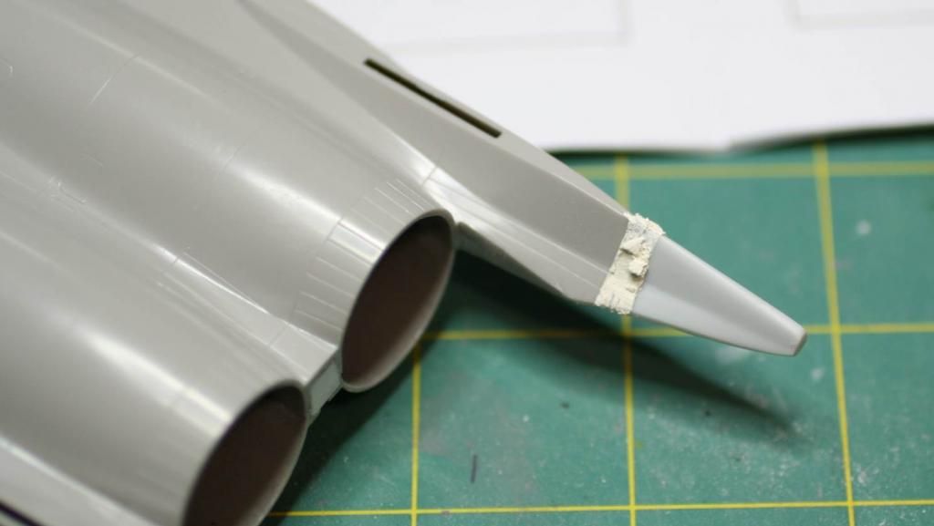
Then I turned my attention to the new antenna mount on the right aft tail. (Yes I was procrastinating on doing the intakes!) I used some 5 minute epoxy to fix the resin piece in place. After letting it sit overnight, I covered the seam in milliput.

Post63_zpsad2b979f.jpg


And then sanded it to shape.

Post64_zpsf577e2bb.jpg


Post65_zps161b7707.jpg


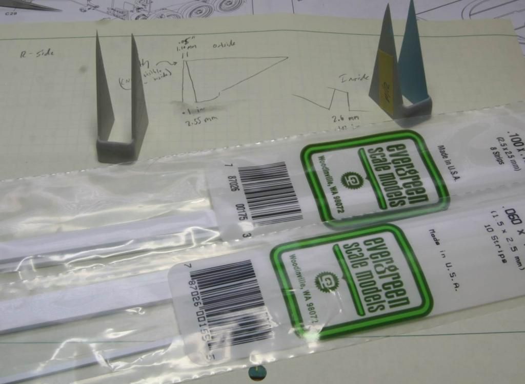
Then I had to finally start on the intakes. Part of my procrastination was waiting on some appropriately sized Evergreen strip to arrive. Unfortunately my local hobby shop closed a few months back, basically with no warning that I can tell, and my next closest is about an hour from here, so now pretty much everything has to be mail order.

Post66_zps10073b3d.jpg


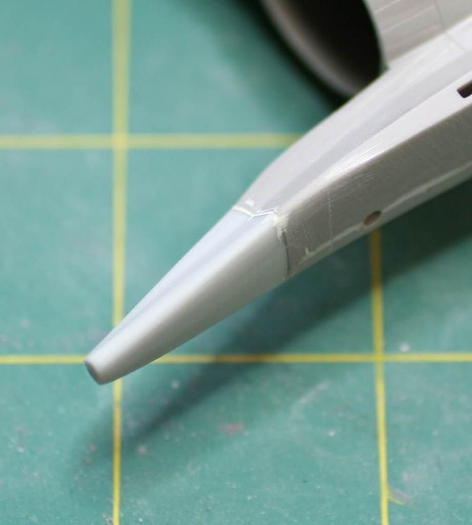
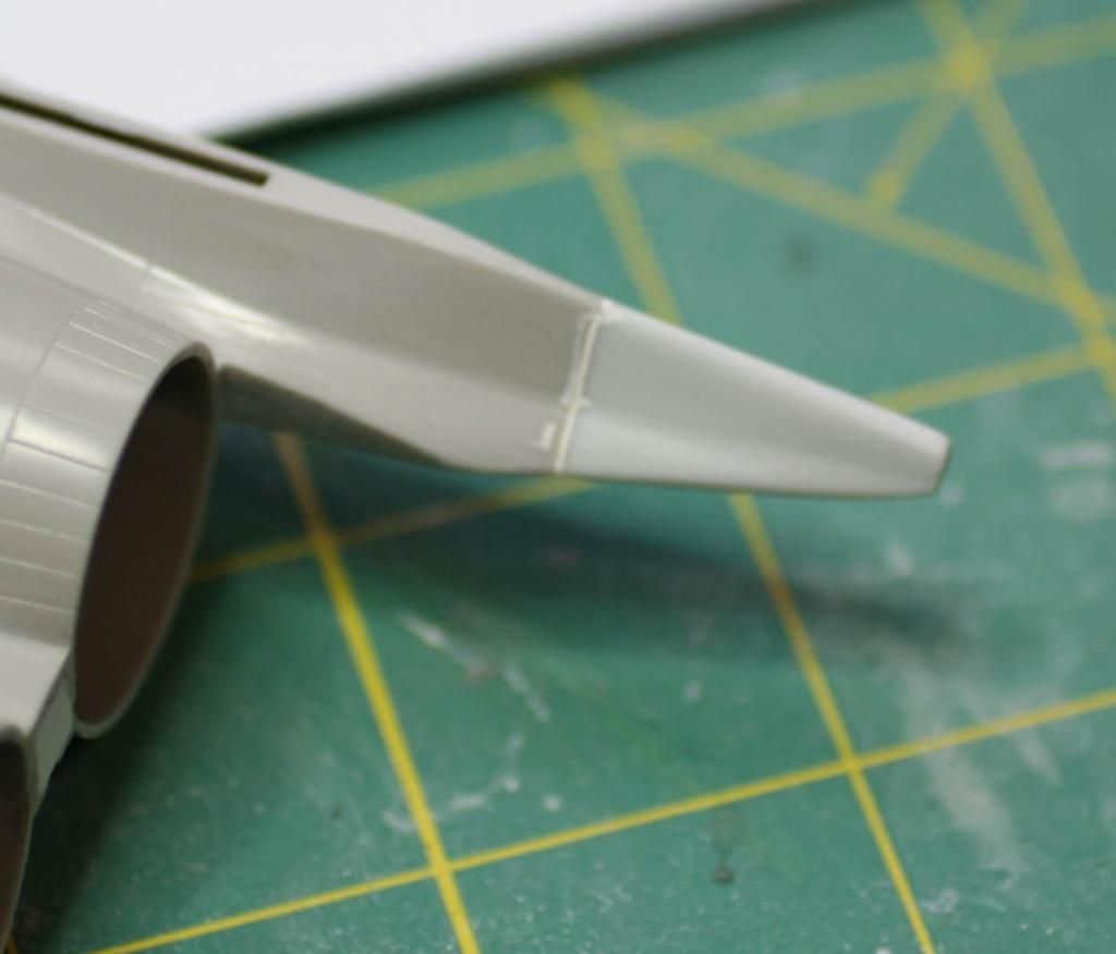
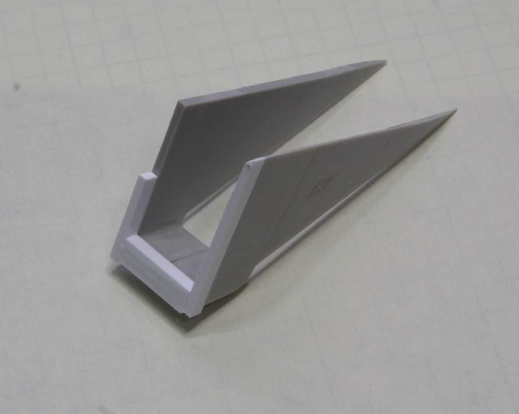
I started with the right hand intake. This had by far the biggest gap. I built up the back end with the Evergreen strip, using CA glue and the Tamiya model glue with the orange cap, to make sure I had a good strong bond.

Post67_zps61c605fb.jpg


I let it sit overnight and then I sanded to shape. I also eliminated the seams on the inside using CA glue and milliput.

Post68_zps1ca393eb.jpg


And I did the same thing on the left hand side intake as well.

Post69_zps64da48bd.jpg


Once all the inner seams were cleaned up I painted the interior and the inner faces in the lighter blue, following my reference pictures. I’m using MM Enamel Flanker Medium Blue.

Post610_zpsc576831f.jpg


Then the intakes were installed on the aircraft.

Post611_zpsf7b9428e.jpg


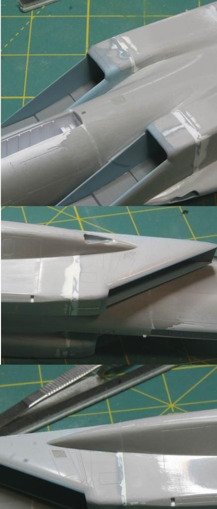
There were still some seams to clean up, but luckily the seam here is in a location on the airframe that doesn’t have any panel lines. So out came the milliput again and the sanding sticks to blend everything together.

Post612_zps5dc8f436.jpg


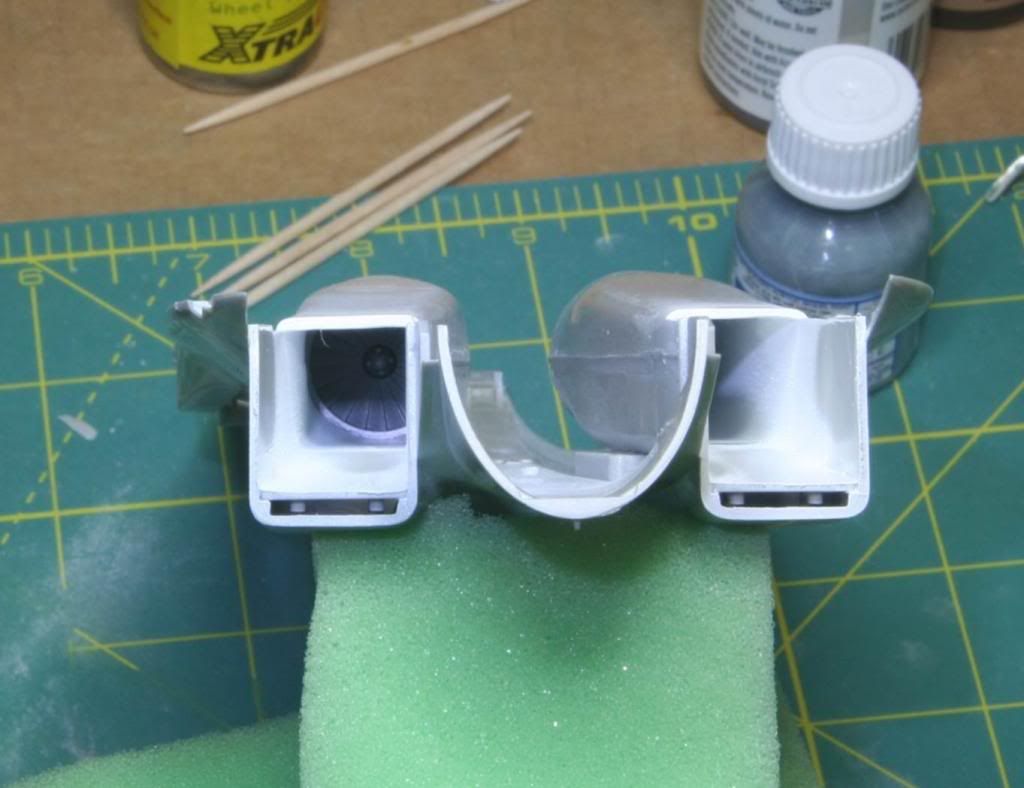
Overall I am pretty pleased with the outcome of the intakes. This was an incredibly difficult part of the kit and I think it turned out really well. I tried to take some pictures down the intakes to show that you really can’t see the joints on the inside, but I just couldn’t get the camera to focus. But it is really hard to tell and I’ll be comfortable leaving intake covers off this Hase F-15!

Next I added the airbrake. It needed to be persuaded to fit in the closed position. Honestly the fit issues don’t shock me with this kit any more.

Post613_zps92217ca1.jpg


And finally I added the wings.

Post614_zps17cb3a30.jpg


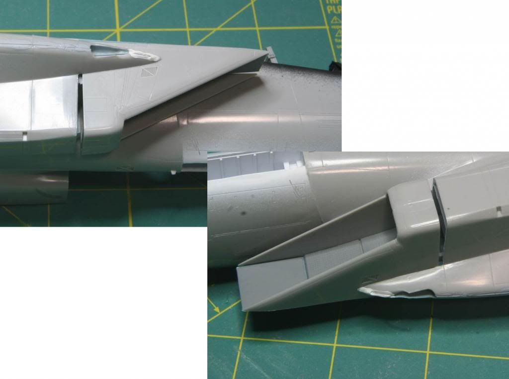
And of course the fit at the wing root is poor. I guess that the next thing to go ahead and clean up.

Post615_zpsb57194c9.jpg


I'm moving along. Hope you keep following!

Mike
 
Love an F-15.... always did !!

https://www.youtube.com/watch?v=oBOXXoDHaVE

Will be watching this build (and You Tube).

Ian
 
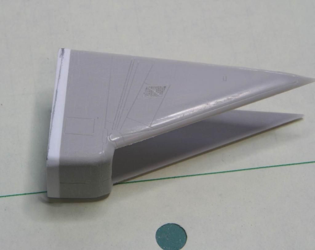
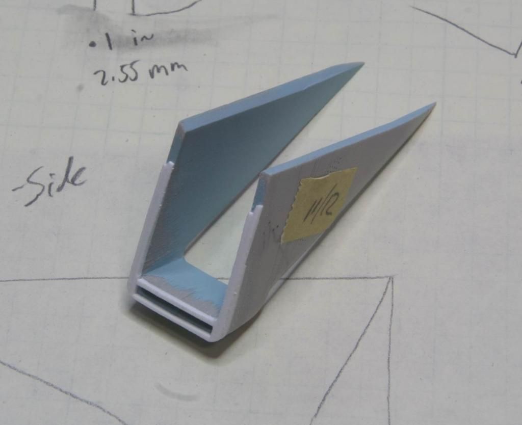
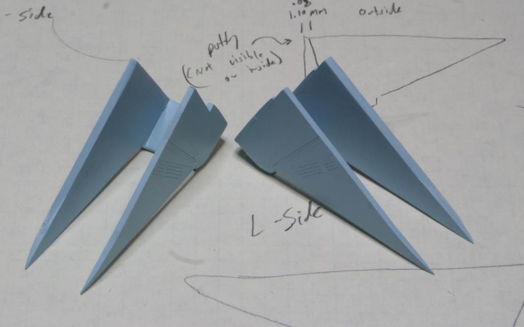
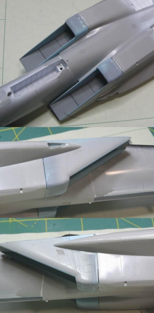
Thanks for the kind words guys! I have to say this kit is just terrible. There isn't a seam on it that doesn't require filler. But on the plus side, I am really improving my skills and learning new techniques to solve fairly unique challenges. Just wait to you see what I'm doing for the wing tanks.

Just to give you all a scale of the timeline, the first post was actually right around the first of the year, so this guy has been going on for about 6 months or so. I am a pretty slow builder in general, but frankly this is a hobby - not a race. :yipee

See you soon!
Mike
 
Very nice! I have that same sheet of decals that I've been wanting to use, but havent had the guts to pull the kit out and get started on it.
 
Really a meticulous work...well done...I ´ll follow with full attention...like the use of the aftermarket parts...congratulations Mike!

:popcorn

Luiz.
 
Very nice work Mike (y) Frankly I would have thought that a Hasegawa kit would have firt together a bit better.
Just learned a couple of things that have nothing to do with modeling.

# 1 According to the decals, the aggressor squadron is the 65 ? Interesting since WA is very much the 57 th or it was while I was there. Maybe the numbers have changed :idonno

# 2 I did not realize that anyone had ever removed arresting gears from their aircraft . Pretty ballsy since it's such a good thing to have when other things fail.
I can't think of any USAF aircraft from the century series on to not have one . Even the Streak Eagle flew with tail hook as far as I know .

Cheers, Christian B)
 
Even the Streak Eagle flew with tail hook as far as I know .

Cheers, Christian B)

If they did they wasted weight cause you remember, they did that record breaking flights at Grand Forks AFB, I don't recall seeing any arresting wires anywhere. Not something that came standard on the B52 and KC135 you know :rotf
 
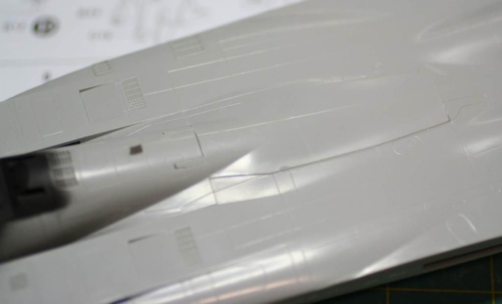
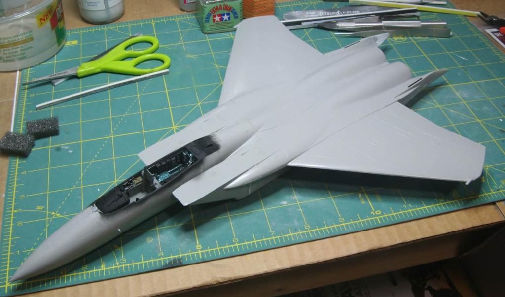
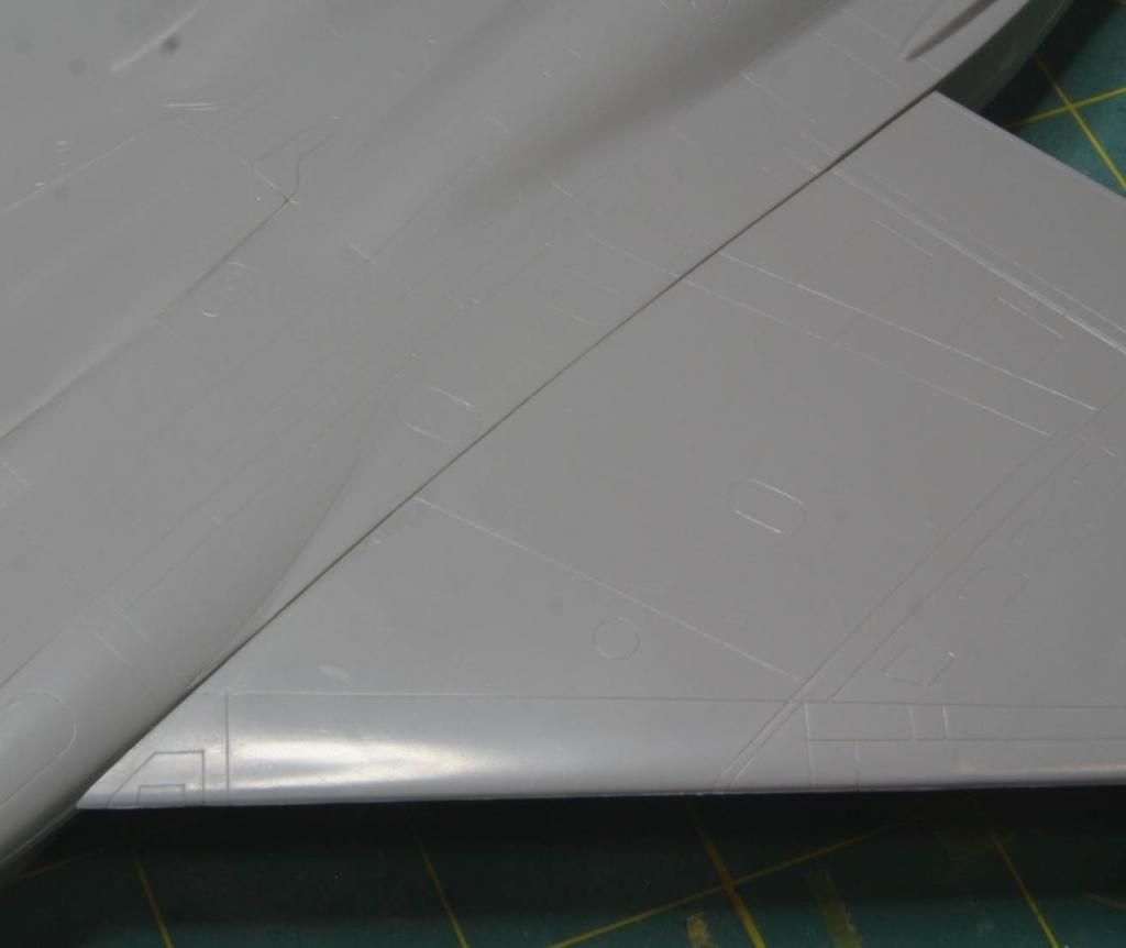
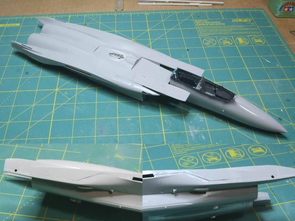
Thanks guys! I really appreciate all the kind words. Just finished cleaning up the wing root seams. Next up is a shot of primer to see how they look...


Very nice work Mike (y) Frankly I would have thought that a Hasegawa kit would have firt together a bit better.
Yeah - this is really a tough kit, but I think the molds are pretty old, like maybe the early 90's, not really sure of its history.

# 1 According to the decals, the aggressor squadron is the 65 ? Interesting since WA is very much the 57 th or it was while I was there. Maybe the numbers have changed :idonno

The 65th was stood up fairly recently at Nellis (2005 i think) from what research I have done. I'm not really sure about the 57th.


# 2 I did not realize that anyone had ever removed arresting gears from their aircraft . Pretty ballsy since it's such a good thing to have when other things fail.
I can't think of any USAF aircraft from the century series on to not have one . Even the Streak Eagle flew with tail hook as far as I know .

The tail hook wasn't removed from the F-15, just the housing that used to be between the engines and over the tailhook. I guess it was part of one of the MSIP upgrades? The Wolfpack kit has a replacement hook that I just haven't added yet.

Thanks everyone for watching.
Mike
 
Even the Streak Eagle flew with tail hook as far as I know .

Cheers, Christian B)

If they did they wasted weight cause you remember, they did that record breaking flights at Grand Forks AFB, I don't recall seeing any arresting wires anywhere. Not something that came standard on the B52 and KC135 you know :rotf

Bob, I don't think the barrier would hold it in full AB. It must have been anchored to a solid point .

If my recollection of the film is still good.....It was tethered to the ground so that it could be run to max AB. before being released.

The release was accomplished via and explosive bolt ( Most have been quite the kick in the pants ).

Could not find a video that showed the separation point

Cheers. Christian B)
 
Hello everyone – I’m back with a small installment on my F-15. I haven’t had a lot of time to work on this lately and my progress shows. :blush:

Well let’s get into it. For an F-15C aggressor, the antennas need to be updated from what is included in the Hasegawa kit. The first changes are on the bottom of the nose. The first was the little nodule located just aft of the radome, then the swept blade antenna was added in place of the straight blade antenna that was molded onto the fuselage. The small antenna, which I believe is for the TACAN was installed next and the straight blade was kept from the molded on kit parts.

Post_7_1.jpg


Next up was to add the upper nodule on the top of the nose, just aft of the radome.

Post_7_2.jpg


This was followed by a clipped antenna just aft of the canopy. On the particular aircraft I am going to build, this is supposed to be a straight antenna, which is what is already molded onto the kit, but I accidentally broke that off. :facepalm Thanks for the spare part Wolfpack!!!! (y)

Post_7_3.jpg


Continuing aft I next installed the GPS antenna. I first cut out a square of .010 inche plastic then mounted the antenna to the plastic and glued it down. Wolfpack’s kit doesn’t really give you any placement instructions for the GPS antenna, so I had to go off reference photos and other peoples builds.

Post_7_4.jpg


Next stop was the tail. First off I added the tail hook and the new structure around it.I drilled a hole in the plastic sheet, cut it out the area for the hook to extend and then glued the hook into the drilled out part. Super easy. I also added the RWR antenna to the ne section of the tail. These parts are all from the Wolfpack kit as well.

Post_7_5.jpg


Next up – I needed to repair a broken AOA sensor. The kit sensors were molded onto each half of the nose and one was damaged out of the box.

Post_7_6.jpg


To fix the sensors, I shaved off both of the molded AOA sensors and replaced them with the AOA sensors from an Hobby Decal F-16 pitot and AOA set that are turned metal. Much more refined. Drilled a 0.5mm hole where the ghost of the molded probe was and inserted the new turned aluminum one. Popped in and looks great. Didn’t even use glue. Really happy with this save.

Post_7_7.jpg


Now I need to work on the glare shield and then get the front canopy on. Started by adding the photo etch pieces for the HUD. These are from the Aires cockpit set.

Post_7_8.jpg


I’ve since gotten the glare shield repainted and detailed, and now I’m wrestling with a front canopy that doesn’t seem to fit, but that’s a story for next time…

Thanks for looking in!

As always – comments and critiques are always welcome.
Mike

:drinks
 
Back
Top