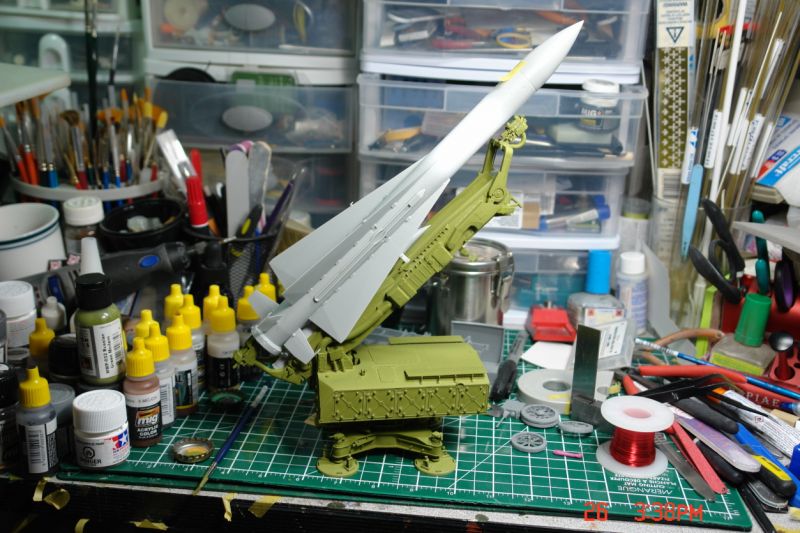
Almost done. Just the tiny parts and paint. Here is a list of things I found that might help anyone else doing this build.
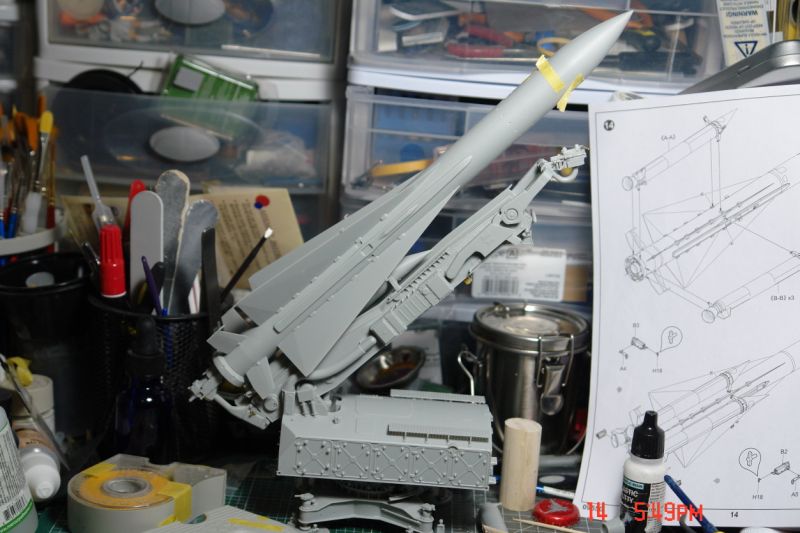
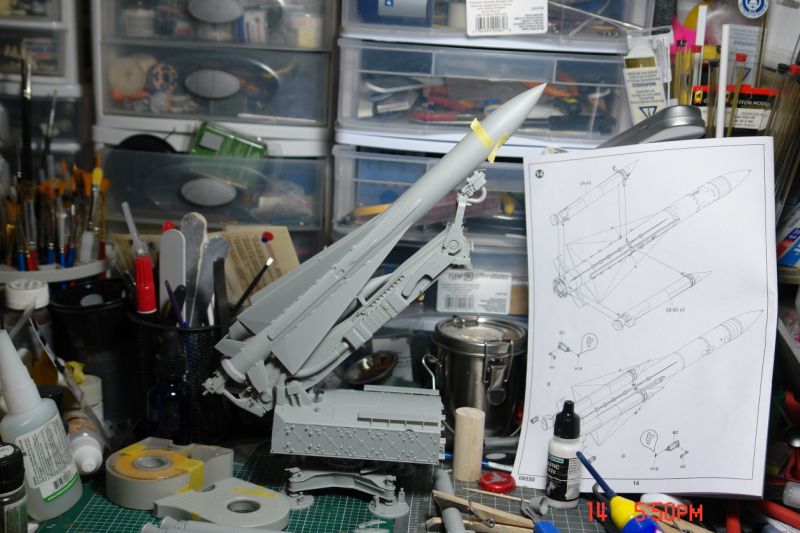
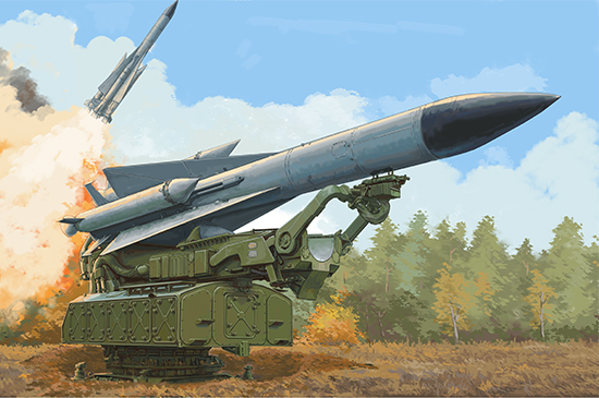
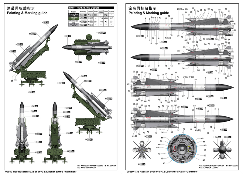
Trumpeter SA-5
Step 1: No issues with this except trying to figure out how the stakes were mounted. Insert narrow end of H20 through hole in stake and into hole in arm with end pointing up at an angle. Think maybe taping the stake to are then doing this may be best way. Note. Most of these seem to be mounted on hard stands so would not use the stake. I finally found pics with all stakes removed. Will have to try and remove the ones I mounted if possible. Found the diagram really confusing with the square box shown on the turn table that isn’t there and not real.
Step 2: Highly recommend DO NOT glue the tiny stuff on until you sandwich the turntable between the crescent parts. Lost pieces on mine.
Step 3: I used some blue tack on the PE-A1 part. Some cyano on end and held on and then some blue tack to hold it. Then continued gluing and adding blue tack until I was done. Worked really well.
Step 4: Leave till last or parts will disappear. I tried Tamiya green cap and it didn’t work well so used the revel glue and it worked very well. Its just controlling how much comes out that is the problem. Found it way easier to glue par A-1 and2 together and mount and then add B-9 and then PE
Step 5: Small parts last. Learned the hard way the mesh stands have really small dimples matching the protrusions on the roof and the little supports (G-21). Screwed up but got it together finally.
Step 6: It was difficult getting the shafts mounted on C-17. Finally figured out that if I wedged the handle of my tweezers into the slot and then turned them I could force the walls apart. H-15 slid in easy that way. Care needed you don’t snap C-17s walls though. Rest was nice and easy
Step 7:
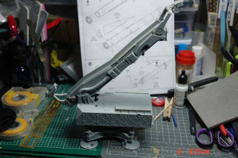
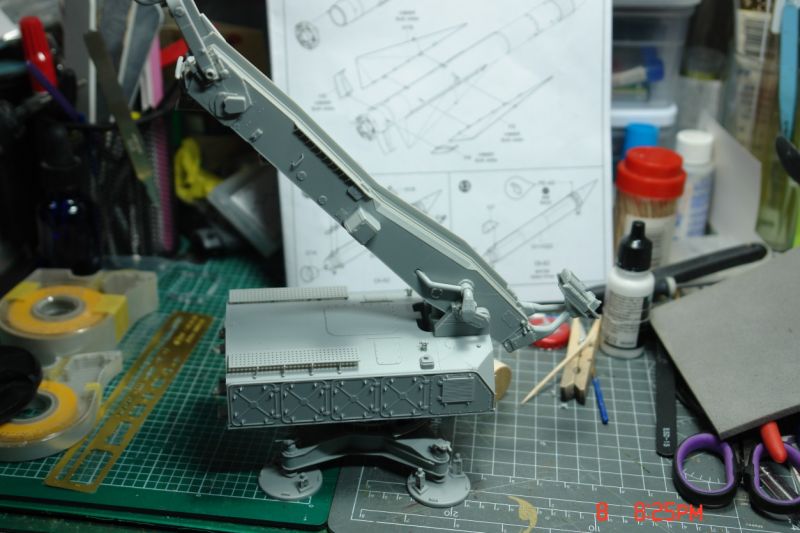
Step 8: B-22 makes no sense. Could not figure how to mount it as shown. But all the pictures I have seen show B-22 being closed on B-16 and the missile resting on the 2 teats so that’s what I did. I used a drill bit to line up the 2 end pieces (B-24/D-15 and C-23/D-4) and then pinned with G-3 and glued G-3 in place. Nice and easy. Also I found it easier to glue the 2 forward arms to H-6 and the launcher and then place the end piece in. Then taped around the 2 arms until set so the end piece can still move. I’ve found it either holding the missile or folded down.
Step 9:
Step 10: C-25 and C-26 hard to install. Had to use some pressure and lube the holes for the pegs with some glue first. Worried I might break it when I was doing this step.
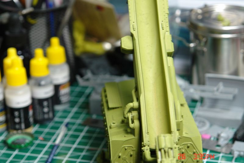
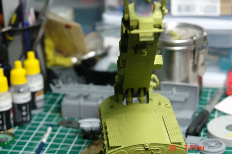
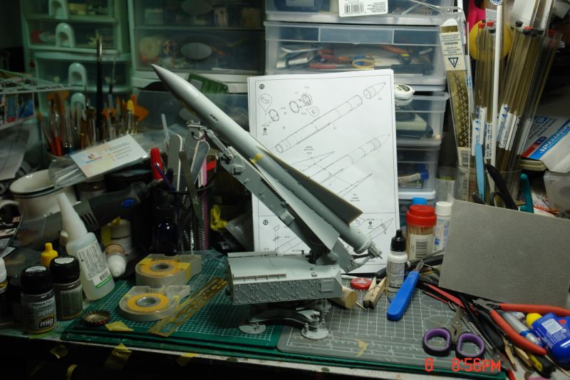
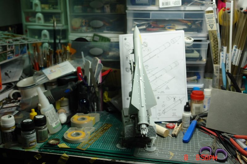
Step 11: Leaving E-3 off so I can paint the missile and head separately. Same the aux rockets will be left off to paint.
Step 12:
Step 13: PE-A5 really small so not sure how I will bend it.
Step 14: Okay B-2 and B-3 confused the hell out of me. Finally I came upon the bright idea to glue them to the launcher and they would line up with whatever later. Bad move. I finally found that they have a socket that the bottom Aux Rocket plugs into and then onto the launcher. Managed to pry them off with no damage. Now they are ready to be glued properly. When I get the Aux rocket painted I will add them and install it on the launcher. Then I will mount the rocket to it. Then add the other Aux rockets. Have done a dry run and that’s the easiest. H-18 is uber tiny.
Step 15:
Step 16: I added E-4 during step 10 so it would all be lined up.
Hope this is of some use to you.
And in the final view you can see the door with 2 mounds closed with the missile resting on it. Thats the most common pic I see.
James


")