• Modelers Alliance has updated the forum software on our website. We have migrated all post, content and user accounts but we could not migrate the passwords.
    This requires that you manually reset your password.
    Please click here, http://modelersalliance.org/forums/login to go to logon page and use the "Forgot your Password" option.

Roden 1/72 C-123B

jeaton01

Well-known member
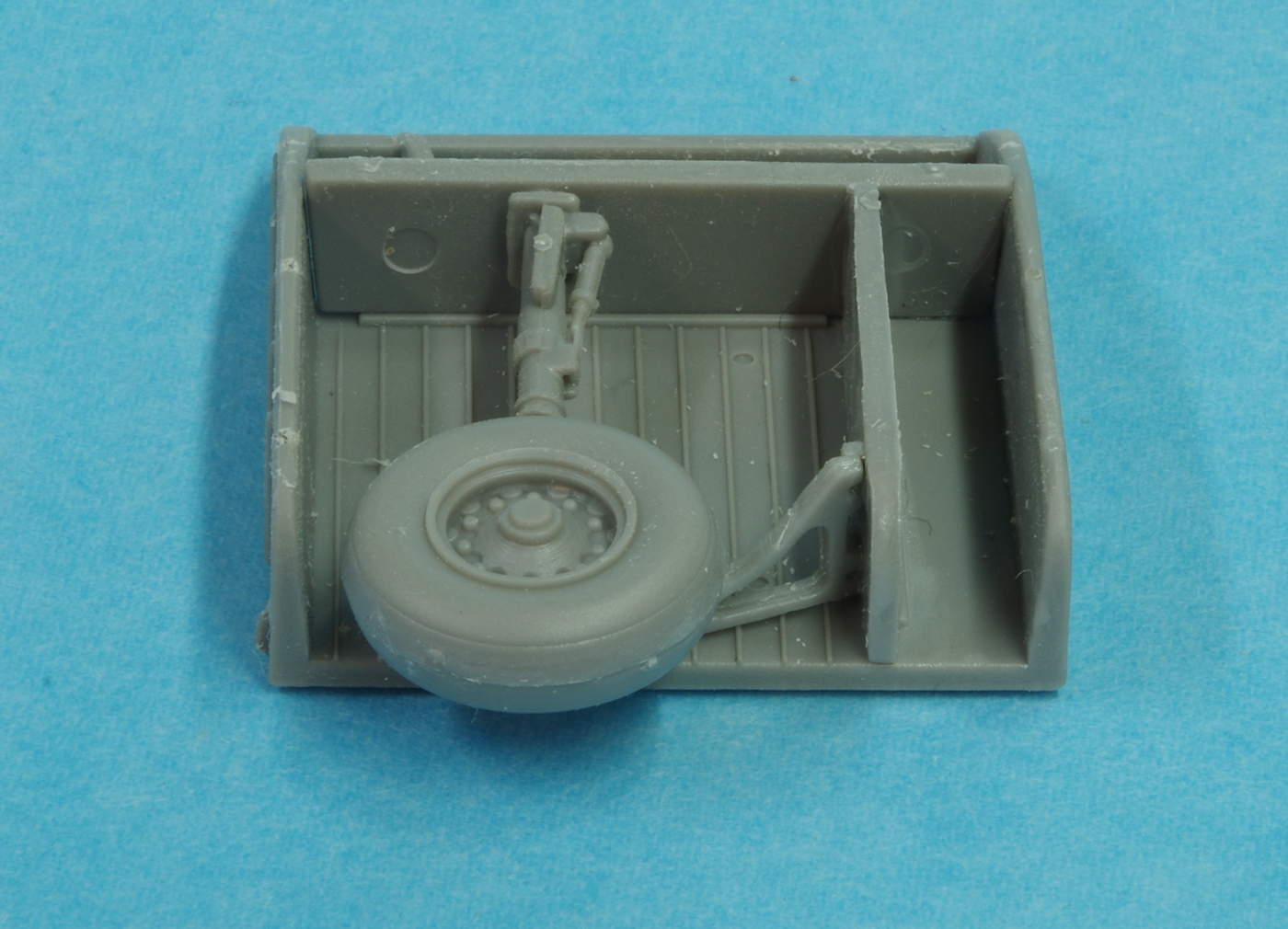
I've made a start on the Roden C-123. It's a very detailed kit, however, I don't think their mold making abilities are quite up to handling the kind of fine details designed into the parts That makes building more difficult. Also, the plastic doesn't seem to like Tamiya thin cement, or CA for that matter. I am using the Testors glue in the triangular bottle right now and it seems to be working, and will try the Touch and Flow Tenax like stuff also. The engines have a lot of detail, most of which will be hidden. I found on assembling the first one that the alignment of the cylinder banks is off, with the rear bank lined up directly behind the front bank, where the rear bank in the real world is offset so the rear cylinders are lined up with the air gap between the front cylinders. It really doesn't matter in this case but being an old engine guy I just couldn't stand it. I didn't fix the first one because I had already glued the front housing on and didn't want to mess it up trying to move it. The pictures show how I modified the second engine. I didn't like their method of attaching the props, I'll do my usual brass tube and music wire method to attach them. The nose gear will ultimately rest on a spider web of struts so a lot of time was spent figuring how that was to be done. The main gear has an odd way of attaching the wheels, they have you put the inner wheel half on the strut, then there is a plastic keeper washer that is glued on to hold the inner wheel half. Then you are to put the outer wheel half on. Clumsy to sand and paint! I assembled all of the main gear parts because I wasn't confident of how the parts fit without doing it all at once. A little misalignment on that narrow gear and the wings will surely not be level. The instructions are not clear enough for me on these assemblies.
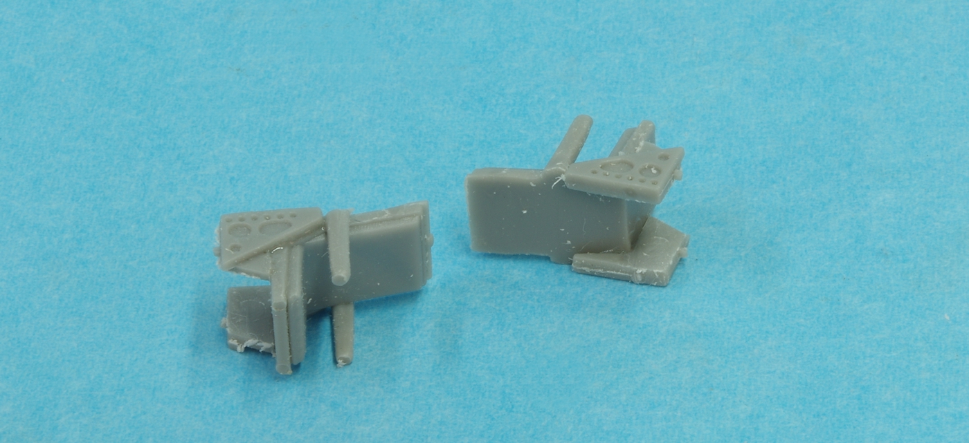
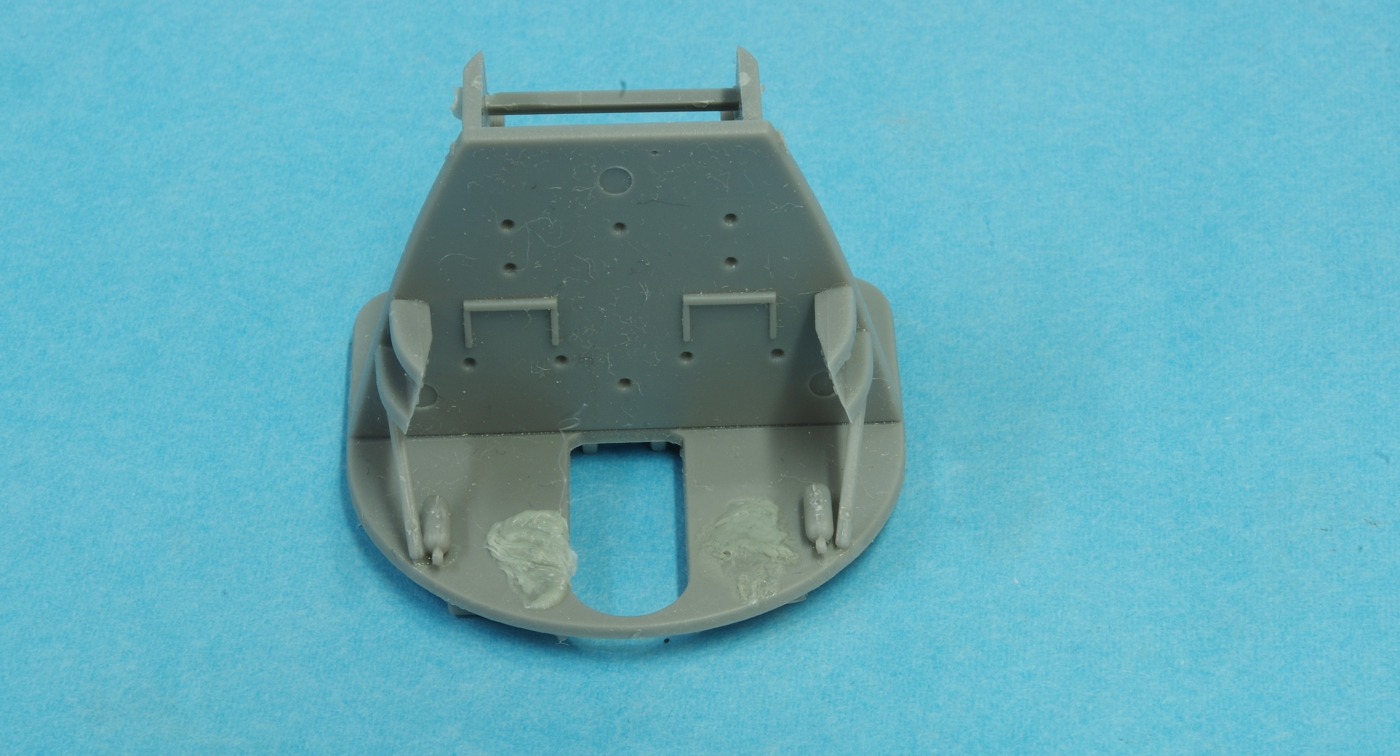
Some of the cockpit parts were assembled and two ejector pin marks on the back wall of the cockpit were fixed using melted sprue.
I made masks for the wheels and windows this afternoon using a Silhouette Cameo vinyl cutter. There will be paint soon!
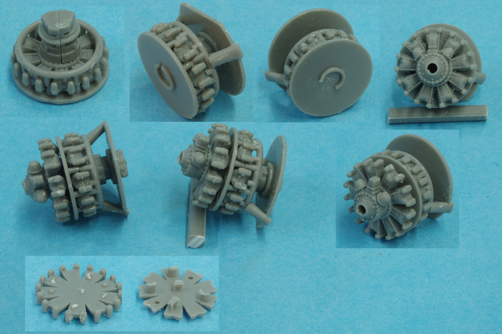
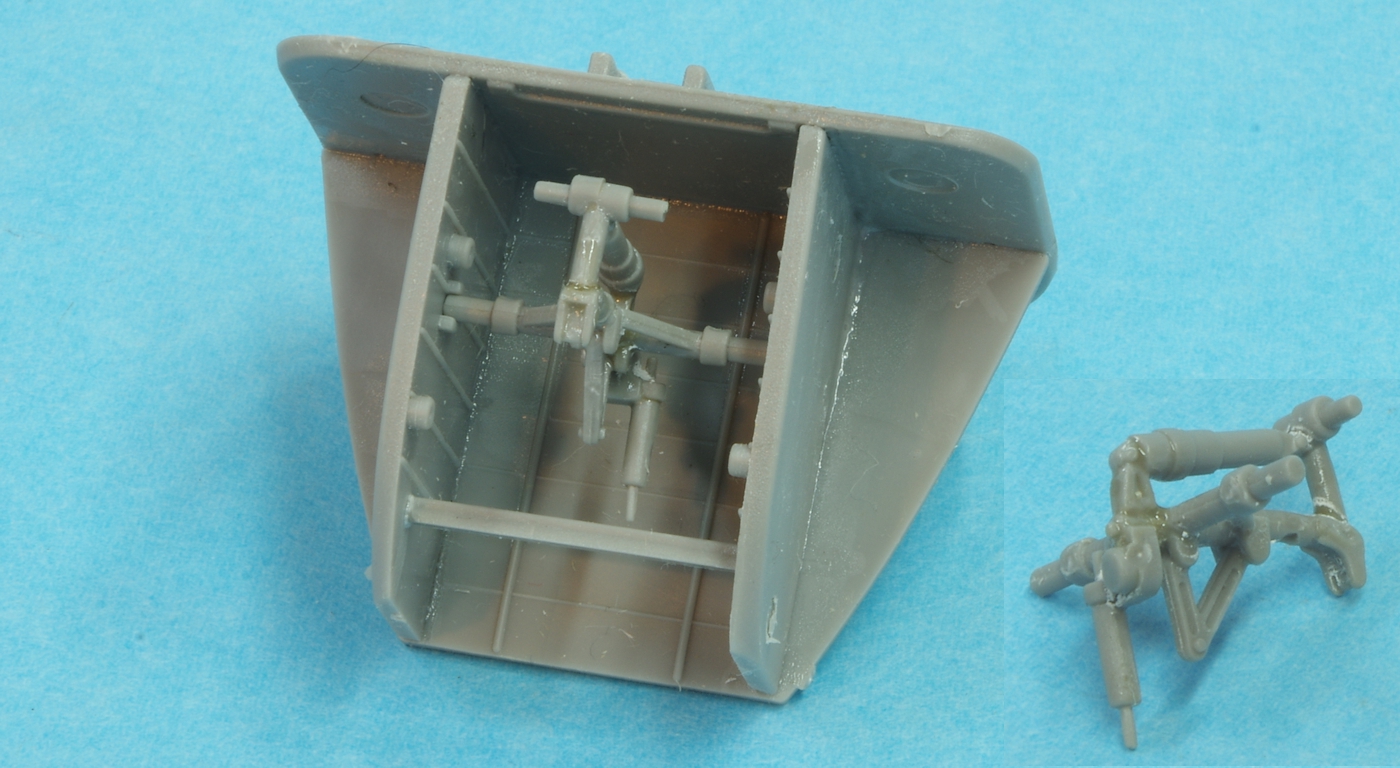
0171c123.jpg


0141c123.jpg


0131c123.jpg


0161c123.jpg


0151c123.jpg


0181c123.jpg


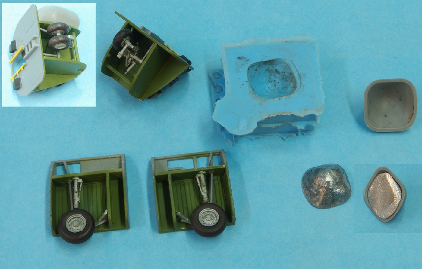
There was no positive locating method for the wheel well assembly so the floor was used to locate it and then lines were scribed on both sides of the well assembly.
Interior green was applied to the fuselage area enclosed by the wheel well. The well is not yet permanently installed.
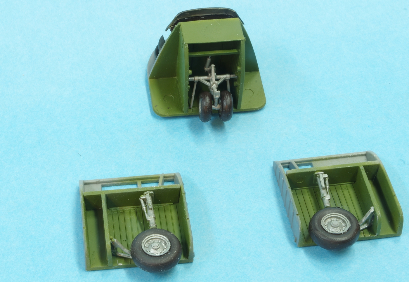
0191c123.jpg


The landing gear assemblies complete and painted. There are some actuator arms for the nose gear doors that the instructions call for at this point but they are going to be left off until the very last.
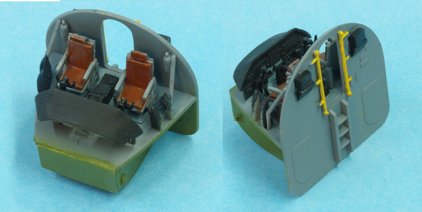
0201c123.jpg


Still a flat coat to go but the cockpit is together and painted. The lower parts below the cockpit floor were painted interior green because there is a window in the fuselage in that area.
20 grams of weight are called for in the nose. A silicone mold is curing and tomorrow a weight will be cast in it. Clay was pressed into the nose cone to develop the shape.
 
I don't think I've ever built a Roden kit but I sure have seen a motor that built up like that, just can't remember what kit.

You'll whip this John, lookin' forward to it. :popcorn
 
I ran into most of the same problems as you did plus some more. I replaced the two struts from the nose wheel to the rear bulkhead with wire as it looked like too much trouble to make them round. I ended up breaking the nose gear off during painting and had to drill out the main strut and reinforce with some brass wire. I found out that after adding nose weight the main gear wanted to splay outward, strut too long and not enough support. I ended up cutting a block of styrene to fit between the wheel and the inside wheel well and glued it in. Painted flat black it's hard to see and only the bottom 2/3 of the wheel is visible anyway. I also had problems mounting the engines. I documented it all pretty well here C123 build Overall I liked the final result but found it to be a frustrating build.
 
Yeah, those main gear wheels have me concerned, Gary. I think I will put a block in there now before I go any further. The nose wheels aren't very well attached to the nose strut either.
Thanks for the link to your build.
 
Thanks, Rob,

After Gary's also and Paul Boyer's comments, I decided to reinforce the landing gear with music wire. .050 wire was used on the main gear, drilling through the upper bulkhead and down into the center of the wheel. On the nose gear an .032 wire was used. It fits into a pocket drilled partly through the cockpit floor and is glued to the back of the nose gear oleo on the back side of the nose gear strut. It will be extremely difficult to see the wires once the plane is finished. The nose weight was cast in the silicone mold, melting some lead in an old ice cream scoop used as a ladle. Heat was from a small propane torch. The back of the weight was filed flush with the back of the nose bowl and when done it weighed 29 grams. The instructions call for 20 grams. We'll see if they are right.


0211c123.jpg
 
Nice fix on the main gear, I had already installed the gear well so my options were limited.
 
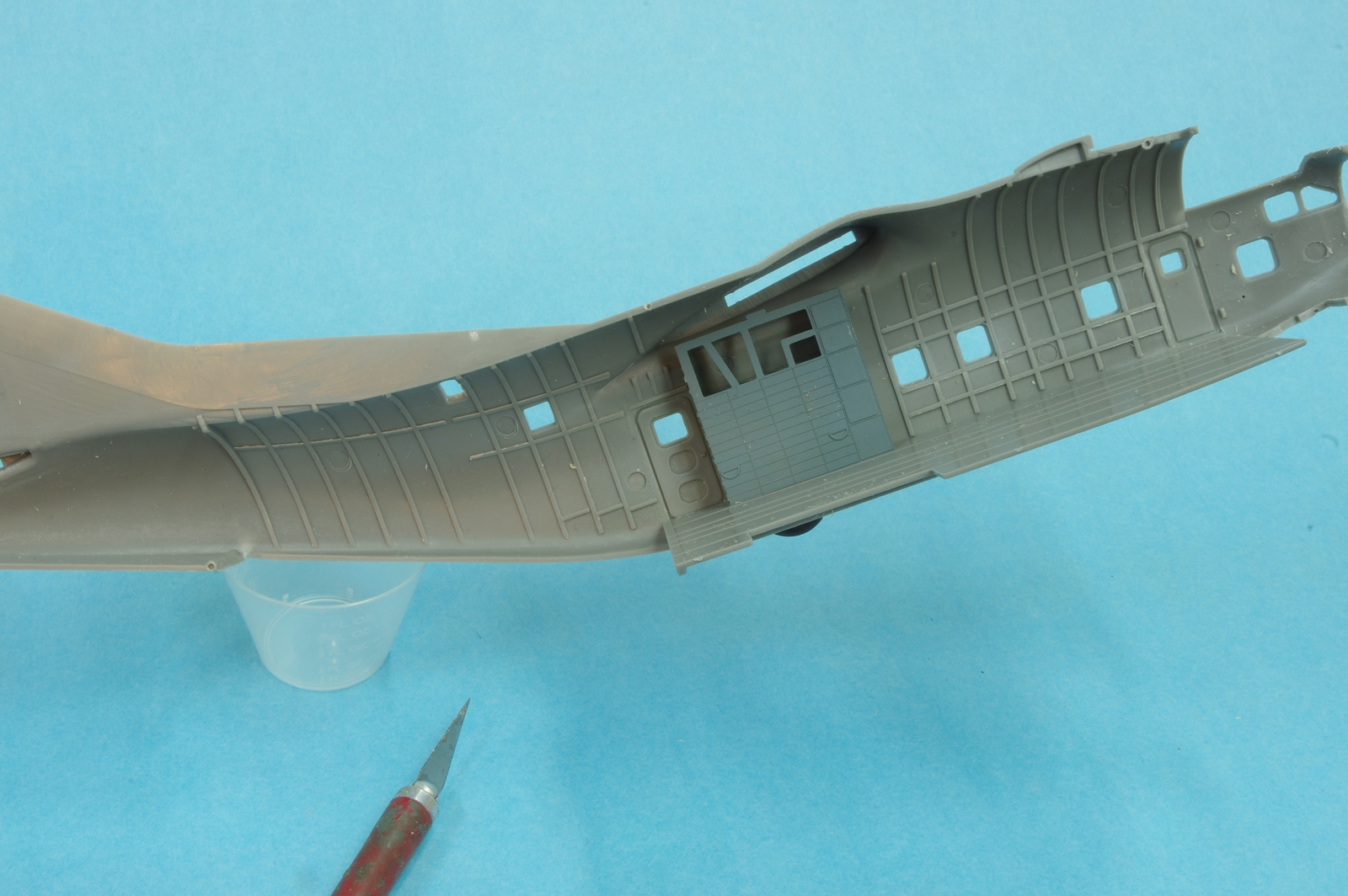
Paul, the Roden 1/144 C-141B was pretty nice to build, and I plan on getting the C-133 soon. But this one is a little more like the Gladiator, the fits are just almost there but not quite. Been fitting the interior of the cargo compartment today and had to take a break after 4 hours or so. Almost nothing got glued together today, just working on fits so the fuselage will close up tightly. I did also get the wings together and the nacelles on them.
 
Paul, the Roden 1/144 C-141B was pretty nice to build, and I plan on getting the C-133 soon. But this one is a little more like the Gladiator, the fits are just almost there but not quite. Been fitting the interior of the cargo compartment today and had to take a break after 4 hours or so. Almost nothing got glued together today, just working on fits so the fuselage will close up tightly. I did also get the wings together and the nacelles on them.

When you do, John, I would really like to know what you think of that kit. I have yet to finish any Roden kit that I have bought. They have a rather high frustration level for me.
 
:popcorn :popcorn
John,
Watching with interest.
I have this kit in the upcoming build pile.
Frank
B)
 
Frank, Gary has a build log on this model also, there is a link to it in an earlier reply he made to this topic. Look for the big eared dog.

0221c123.jpg


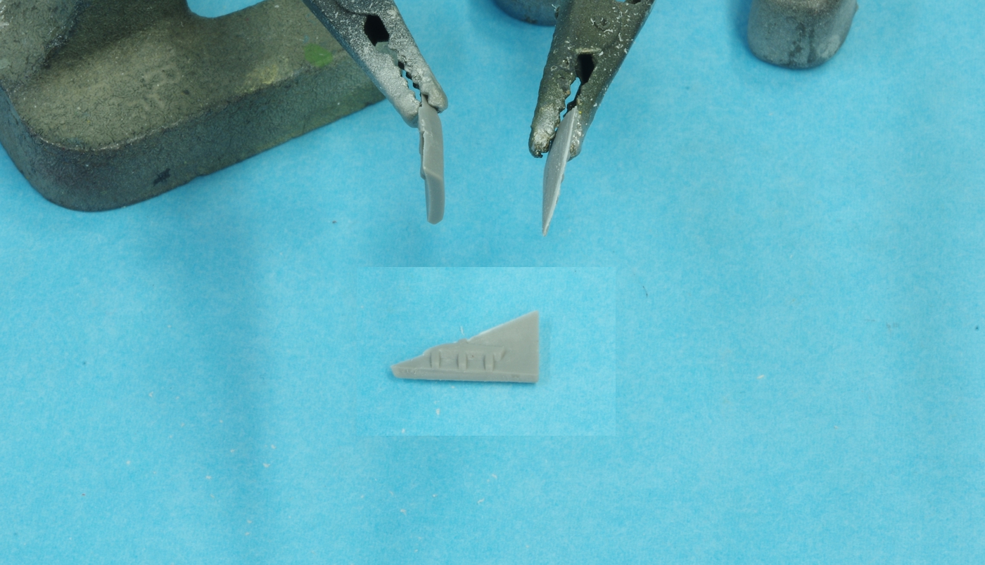
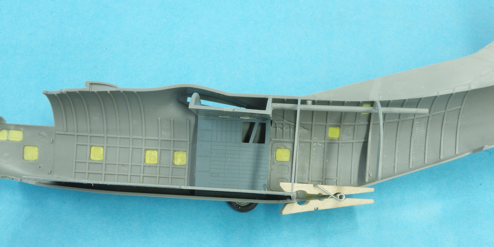
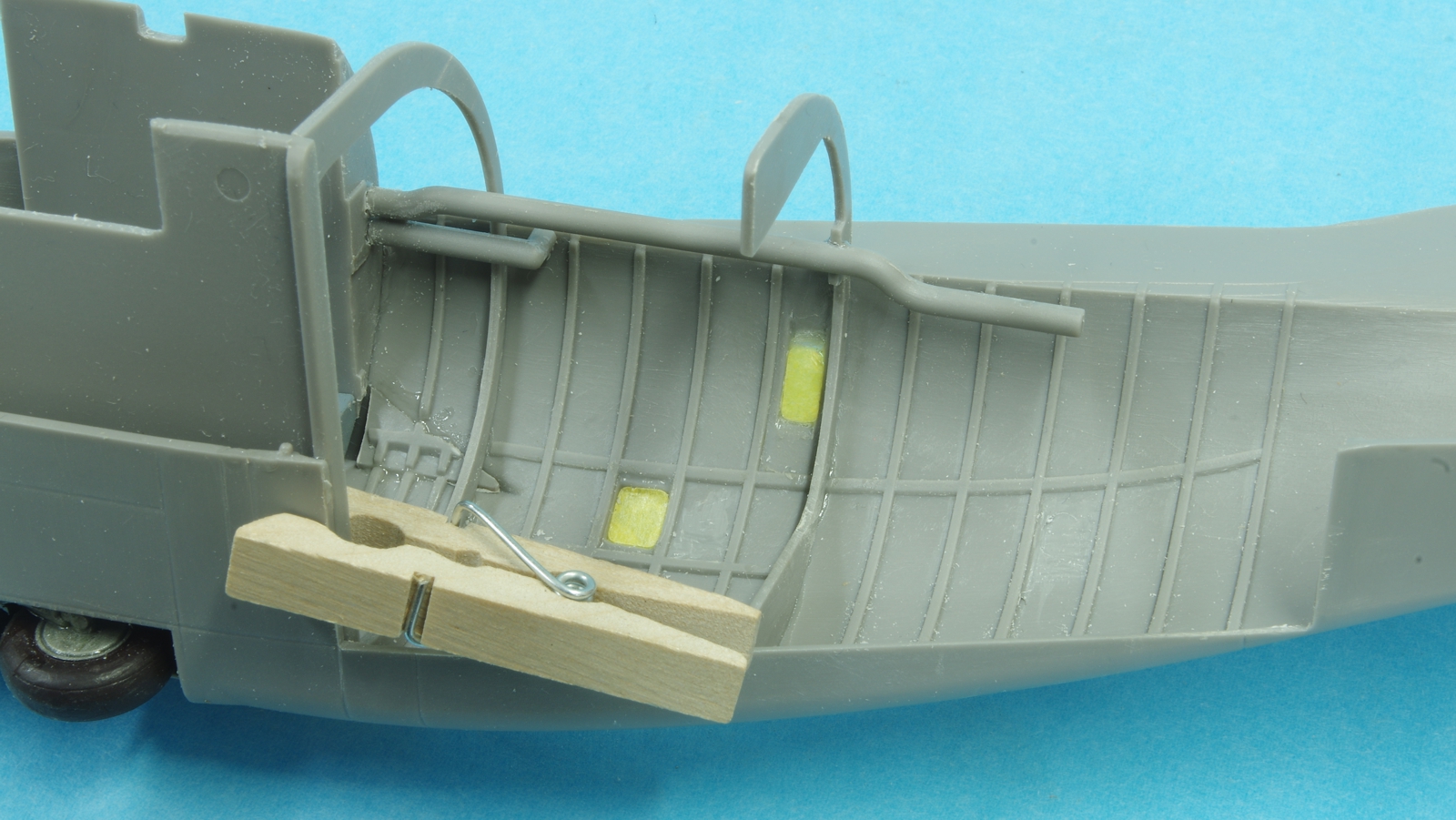
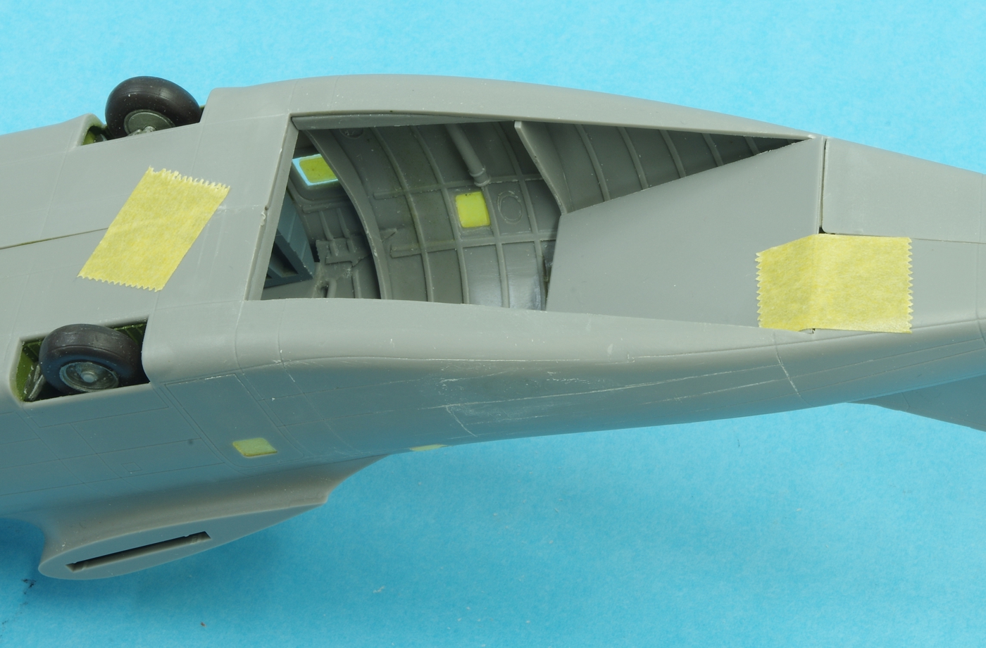
This little triangle fills in the wing root area aft of the wheel well housings. It needs to be thinned down until it is a near wafer, and has to be trimmed back on the side facing the wheel housing to get it to fit flush with the skin and in line with the rib detail. The style of instructions is not helpful as there is no suggested order of assembly within each section of the instructions. The wheel well housings should be installed first, using the floor as a guide to alignment. Get them to fit as flush to the wall as you can because any gaps here will prevent the proper fit of the floor and overhead bulkhead. Then the triangle above should be installed, followed by fitting the floor and the the overhead bulkhead that fits above and between the wheel housings. Dry fitting is needed at each step as the fuselage would not come together freely until the floor was trimmed a little along the sides an in the cutouts where the wheel housings fit. A little filing was done on the top of the overhead bulkhead, and at the cutouts that fit against the wheel housings. Not much is needed but if you don't it will result in a difficult fuselage seam. Next the fuselage frames can be installed, and then the heater ducting. Everything was glued to one fuselage half during the fitting process. It was necessary to remove a little material from the front of the floor before the cockpit and nose wheel assembly would fit properly. Just for insurance about 1/32 was removed from the front of the cockpit assembly to be sure the nose weight would fit without interference. The cockpit glareshield had to be trimmed on the front and sides, and the area of the fuselage under the front of the windscreen was thinned down considerably before the fuselage would come together at the top of the nose.

0231c123.jpg


0241c123.jpg


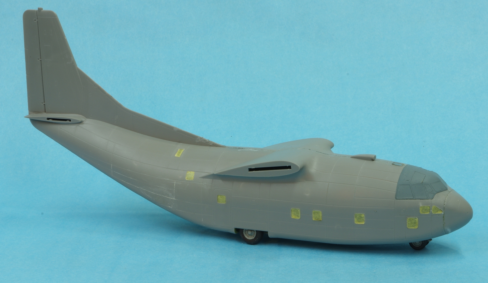
Parts are glued to the right side. Windows are masked on the inside and outside at this point. The masks were developed from photographs of the model, drawn in Autocad, and cut with a Silhouette Cameo from sheets of Tamiya masking material.

0251c123.jpg


Another test fit. The cargo door and ramp have been cut apart and the rear door is trial fitted. The floor sections on both sides of the ramp area are installed, resting against the main cabin floor. For ease of assembly some thin plastic tabs were added at the aft end of the door. The front end will rest on the aft fuselage frame.

0261c123.jpg


Almost anticlimactically, the fuselage is glued together. The interior was painted grey inside using Tamiya Light Grey, except for the floor and loading ramp which was sprayed Floquil Nato Black. Inside window masks were removed and the fuselage seam was joined using Touch and Flow which reacted well with the plastic. The 29 grams of weight will make it a solid nose sitter even with the wings and tail added, and the cargo door and ramp.

0271c123.jpg


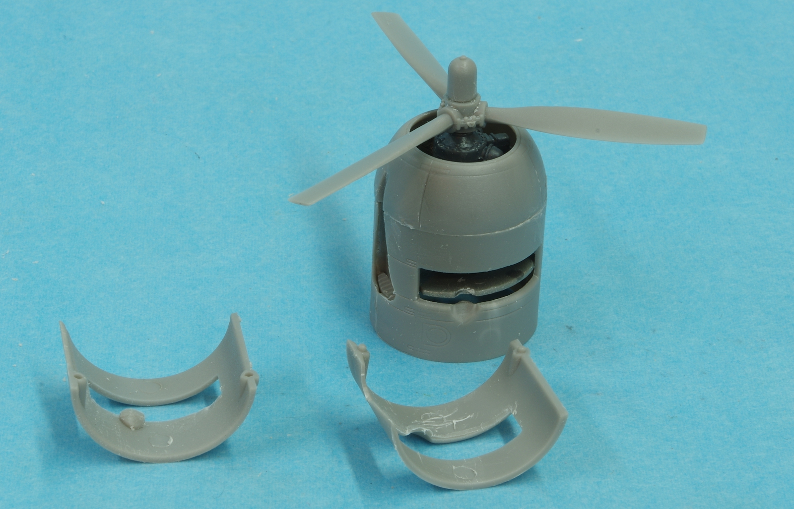
The engine assembly sequence, like the fuselage interior, is poorly set forth in the instructions. It was necessary to remove the locating ridge for the firewall from the cowls and thin down the inside of the depression for the exhaust pipe before the engines could slide into the cowl. The firewall was too far forward and not perpendicular to the thrust line. In the end the engines ended up in the right place but the firewalls are too far forward. This would matter only if the cowl flaps were opened. I would suggest a better way. When assembling the engines, do not attach the firewall to the engine during engine assembly. Do not install the exhaust stubs. Replace the accessory section that fits into the back of the engine with plastic or brass tubing that fits in the hole in the firewall. The accessory section is not molded well enough for the accuracy of fit needed. When the engines are complete and painted, assemble the cowl, nose bowl, and oil cooler duct. Next put the engines in the cowl as far forward as they will go and slip the firewall into the back of the cowl and over the tube that replaced the accessory section and glue it up against the locating ridge in the cowl. Installing the propeller will help in positioning the engines in the center of the cowl and at the proper distance from the front of the cowl. Tack glue the tube to the firewall and check the engine alignment as the glue sets.

0281c123.jpg


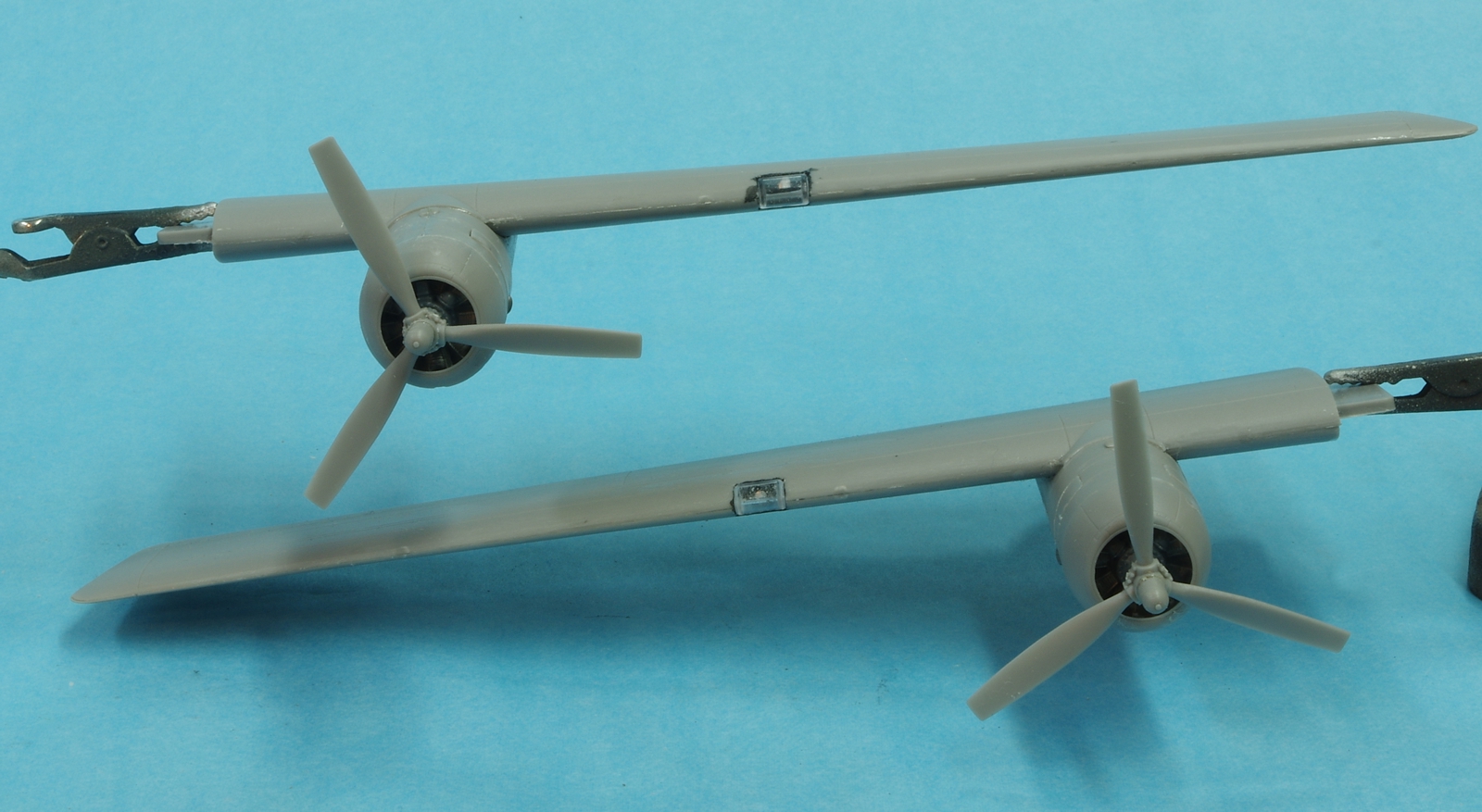
Engines installed to the wings. When assembling the nacelles a fair bit of material was scraped and filed off of the nacelle top to get the the nacelle to fit the wing properly On one side more material should have been removed from the top side of the nacelle and some remedial work will be needed where the wing meets the nacelle. The other side is a good fit. The landing lights fit well after filing the openings for them in the wing.
 
Sorry I missed Gary's mention of the build.
Checking it out this evening.
Thanks for the heads up
Frank
(y)
 
John I also have one of these in the build queue so I'm following along closely as well. I'll also be checking out Gary's build as well. Keep plugging along man, it's all looking great so far!
 
The C-123 is blue at the moment. Model Master Ford engine blue, to be exact. Blue is the color I like for the undercoat for aluminum, although the Ford blue is a little lighter than I have used before, but it's glossy and I have lots of it from the paint stock of a closing hobby shop I bought out. Lots of Mercedes silver too, but I haven't found a use for that as it doesn't match my Camry's silver.
 
Back
Top