• Modelers Alliance has updated the forum software on our website. We have migrated all post, content and user accounts but we could not migrate the passwords.
    This requires that you manually reset your password.
    Please click here, http://modelersalliance.org/forums/login to go to logon page and use the "Forgot your Password" option.

Hobby Craft HC6001 USMC M1A1 Abrams

Tankbuilder

Active member
Shalom.

I started posting this thread over in the Help section to get some help. That thread started to morph into a build thread. I figured it would be better to have it here as the build progresses and new problems or issues crop up. I originaly didn't plan to do a build thread but a number of images have been posted in that help thread. Based on the replies there I figure there might be interest in how this build turns out.

I'm not an M1 Abrams expert but I have had to do some extra research online to find out what some parts in the kit were for and also to help with fixing some issues.

This is actually a repop of a Trumpeter kit and it would be great if, and I repeat IF, you want to build an early M1A1 variant and/or a training version of that.

You get both vinyl band tracks and link and length tracks. You also get poly hub caps to hold the wheels on. This is too bad since that means there is a gap at each hub cap that should not be there.


A BIG problem with this kit is that the instructions do NOT tell you which parts are for the training variant. Thus it'd be very easy for someone to build the training variant and then place the completed model in a Combat setting.

For the training variant you get 3 extra assemblies:

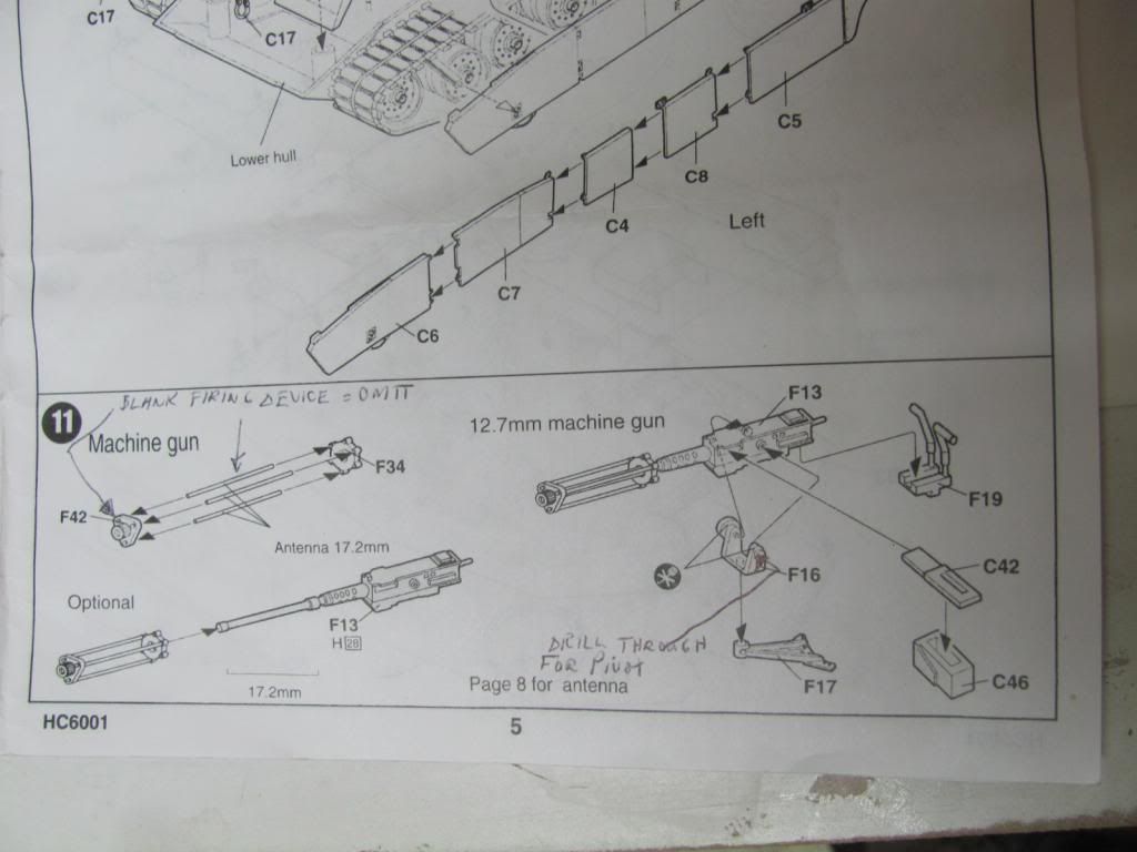
A blank firing device for the ma deuce .50 cal machine gun.


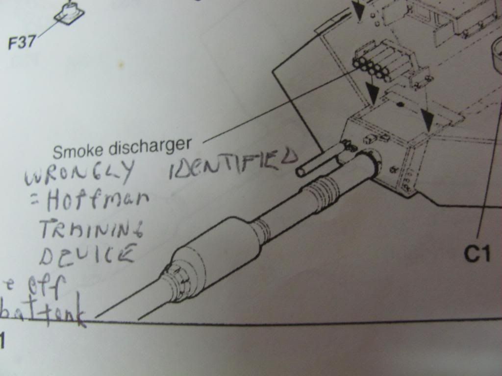
A Hoffman Device for the main gun.


A signal Lamp that registers hits.


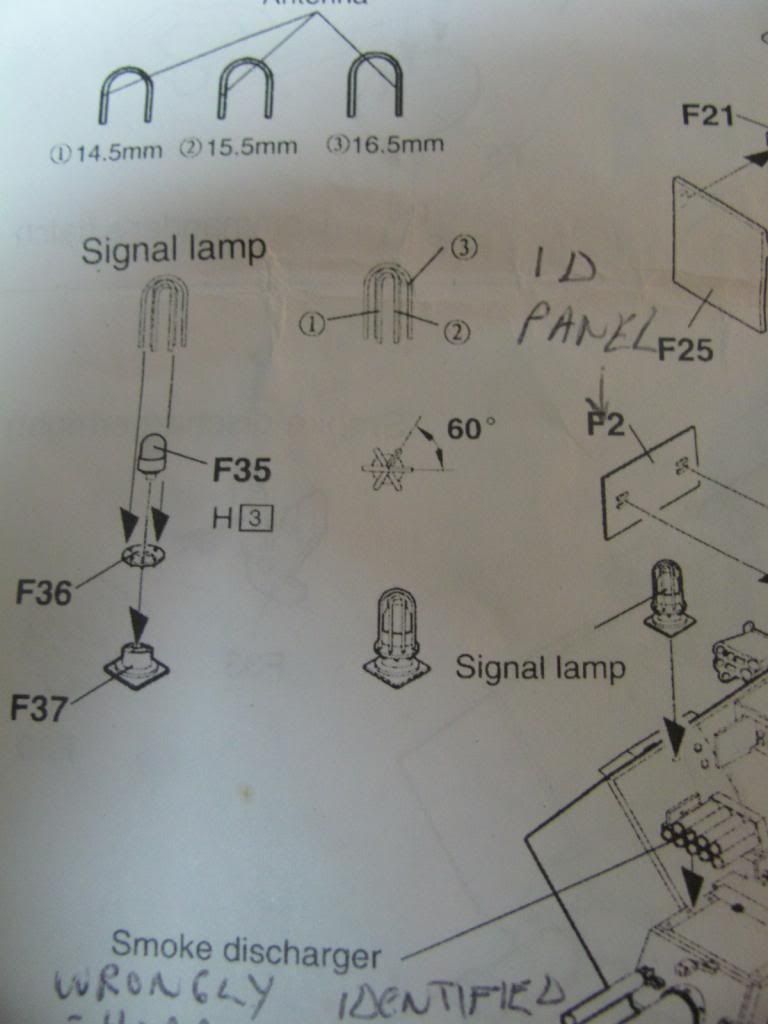
Note that you have to make the 3 rods for the blank firing device and the 3 loops for the signal lamp.


Included parts that make this an early M1A1 variant are:


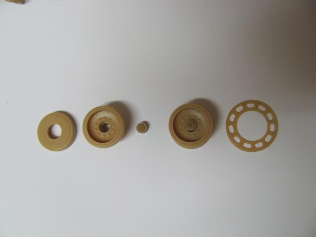
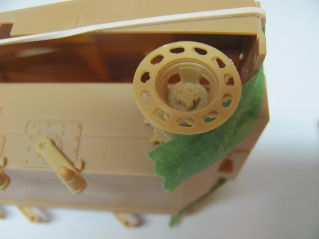
Track retention discs for the two drive wheels.

In place.


Without.


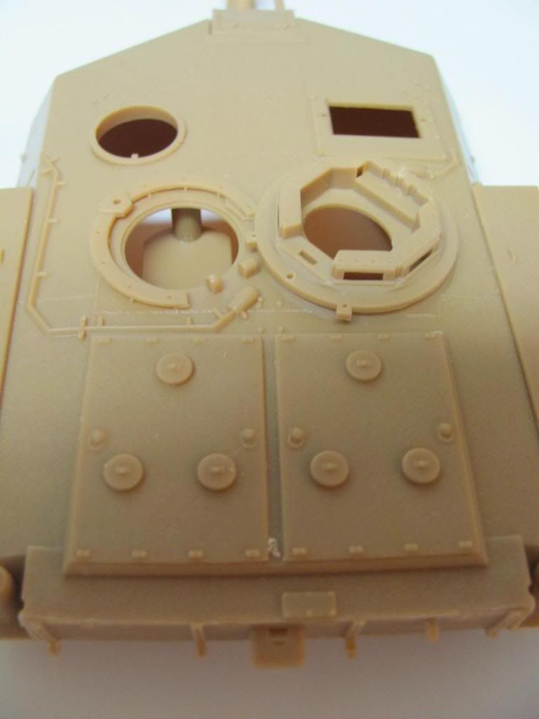
Early style turret roof blast doors. These are the panels with the 3 round raised objects


A rear hull plate mounted Auxilary Power Unit (APU).


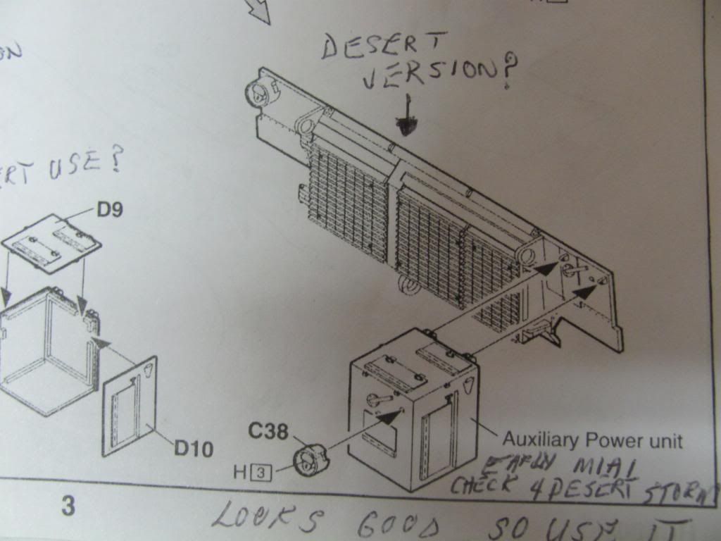
The instructions in this kit would be a lot better with some of the drawings from a different angle so that much of the guess work would be removed.

I had to use short bar clamps to get the rear turret piece to fit properly in the opening left by the turret roof and bottom. When I first assembled it there was a gap about 1 mm high there at the bottom.


Speaking of gaps. The Periscope housing in my kit vaguely resembled the housing shown in the instructions. I had to sand off the two uneven sides to get a smooth side on each side that would then fit flush to the turret roof. The doors that protect the periscope are also recessed in this housing. This means that the gap visible in front of the periscope and on the roof needs to be filled.


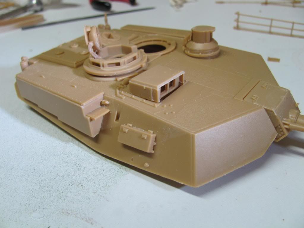
When I get that gap filled and the doors put on I'll post another image of it. The periscope housing in the above image is only dry fitted to the model.

Comments and or questions are welcomed.

Cheers from Peter
 
Those early Trumpeter/Hobby Craft kits will test your skills. Still for the price they can be built to look good.

Which version are you doing?

:soldier
 
Those early Trumpeter/Hobby Craft kits will test your skills. Still for the price they can be built to look good.

Which version are you doing?

:soldier

Shalom.

Funny that you should ask that as I just came on to tell people that I have decided to build it as the early version with the track guard on the drive sprockets. I'll also use the Auxilary Power units. Unless I'm much mistaken the parts are not there to build a proper U.S.M.C. variant.

I don't know about testing my skill, but it sure is testing my patience at times.

Cheers from Peter
 
Shalom fellow modellers.

I have made some more progress on the turret and it's nearly ready for painting.

The turret.

Top view.


Left side view.


Rear view.


There is a device that goes on a little shelf at the back of the rear turret wall. There is a tall part that goes on this shelf. That part is the wind sensor and it's molded in the center of its plate when it should be offset to the left. I cut mine off and moved it to the left. Here is an image of it before and after.

Before.


After.


In place on the rear of the turret.


I was very lucky to locate one really nice image of a M1A1 Early Variant and have decided that's the tank I'll model. Now I'll have to scratch-build some extra things for the extra stowage.

There will be brackets added to the left turret rails to hang soft stowage, a spare road wheel and a cable reel from. This tank will have LOTS of gear piled on it.

I'm not posting that image here due to not wanting to infringe on copyright.

Comments are welcomed.

Cheers from Peter
 
Shalom mates.

I did the base coat of paint on the model and am waiting or it to cure before taking images of it for you.

In the meantime I'm thinking about whether to use the kit vivyl tracks or the kit link and length tracks. Either are weird.

Here's an image of a section of link and length track I'm experimenting with.


This is just a test at the moment to see what it might look like.

The metal on the tracks in tthe image I'm using as a basis, is quite rusty. That's why the lower section of track is painted Rust. I've removed the round protrusions on the lower section but you can still see them on the unpainted upper section. I've also chipped the rubber pads to try and make them look like they've seen a lot of use in the desert.


Here is another image that shows some of the pads painted flat black and drybrushed with a very light grey.


Comments are welcomed.

Cheers from Peter
 
I would suppose that with the link and length you only have to clean up the pads that are visible. Looking good so far Peter :popcorn
 
I would suppose that with the link and length you only have to clean up the pads that are visible. Looking good so far Peter :popcorn

Shalom Moon Puppy.

That's one thing that I *LOVE* about sideskirts - they really cut down on the amount of track you a) have to clean up or b) even use. VBG As you can see in the unpainted portion, there's a lot of cleanup needed on these tracks.

I'll be adding full runs of track and think I'll use the link and length because paint sticks to those better than it does to vinyl.

I need to shine a strong light into the turret from underneath so that I can locate the hole I need to drill in the turret roof so I can add a flag pole and then put a Jolly Roger flag on it. The image of the tank I'm using as a reference has a lot of rust on it and is quite weathered besides having the turret baskets loaded with stuff. All that will add some green colour and rust and browns to the desert colour scheme.

Cheers from Peter

I've done that, forgot to drill out a hole, good idea on how to find it again! :good:
 
Track Pads Distressing.

Shalom.

I'm making good progress on distressing the rubber pad sections of the styrene link and length tracks.

I'm using a #11 hobby knife blade, a chisel-like edge I filed onto a tool I have, and also a triangular sewing machine needle that is held in my pin vice.

The triangular needle has become my favourite tool for applying the chipping at the edges of the track pads. Depending on the angle and the pressure the needle will push a small bit of styrene off the pad and still leave a bit attached. Here's an image of the needle being used to chip the pad. You can see a bit of styrene being cut by the tip of the needle. This is a #11 needle.


In the lower right of these images you can see the chisel edge I filed onto my other tool. It's used to gouge out larger chunks from the pads and also to add the chips to the the areas other than the edges of the pads.


Distressing these pads is tedious but I think it'll make the finished and weathered model look a lot better. With luck and persistence I'll have the tracks distressed tomorrow and will then be able to distress the tire sections of the road wheels attach them and the tracks to the model.

Comments are welcome.

Cheers from Peter
 
Track Pads Distressing.

Distressing these pads is tedious but I think it'll make the finished and weathered model look a lot better. With luck and persistence I'll have the tracks distressed tomorrow and will then be able to distress the tire sections of the road wheels attach them and the tracks to the model.

Comments are welcome.

OK,Peter here is my comment: (y) :notworthy
;)
It certainly sounds like a time consuming job,first time I have seen this technique, really like the way it is hadding.

The funny thing is that a lot of this labour of love will not be seen when it's found it's place on a base.Many times I also do work on the underside of vehicles or the spaces behind tracks,what will not be very visible...my reason for this might sound corny;It's fun to do so!
And that's a great thing about forums;you can show pictures from that work to prove what you did.

:soldier on,Peter.


Greetings,Ron.

Shalom Ron.

I'm only distressing the inside of the pads of the lower run and the outside of the pads where the tracks come up the drive and idler wheels. Any track links that are hidden by the side skirts will not be distressed.

Funny thing though is that the triangular needle works very well and makes it much more enjoyable to do this. It gives a lot more control.

Cheers from Peter
 
Back
Top