fledermaus
Master at Arms
Hi my friends!
Work on the Meilerwagen continues, more details added on different areas.
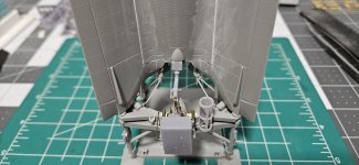
the rear air tanks for the brakes received some details

the air valve is 3D printed

the valve is glued to the frame, brass wire is used to make the air lines


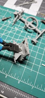
next the rear wheels boogie received brake lines details


I wanted the rear boogie to turn so I cut the shaft and replaced it with a longer one made from styrene rod.

the brake line tee is added

next I tested the locking bar for the rear boogie and found it to be shorter than needed for it to work, also constructed the channel were the locking bar "locks"
the kits locking bar

the original bar and the styrene channel

the channel is glued in place


the new 3D printed locking bar

the bar is drilled and a piece of brass wire used as the pivot bolt
also made the bases for it from styrene


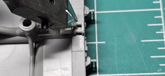
the locking bar is glued in place, here the new styrene shaft can be seen

a handle bar is made from brass wire, it moves!

another view of the channel location

here the bar can be seen in its unlock position

and in locked position to prevent it to rotate

side view of the locked bar

Now the front locking bar is also modified so it works
I started by cutting the bar from the lock frame


the pivot ball is drilled to accept the new styrene shaft

the molded on lock pin for the shaft is removed and replaced with a piece of wire


the new shaft is glued to the frame

here you can see how it works
the shaft is inserted on the pin so the boogie can turn

here the locking bar is lowered and secured to the front of the boogie so it cant turn, this is used when you want to pull the trailer from the back. the bar pivot lock pin isnt attached yet.

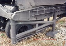
some of the reference photos
here the front locking bar in locked position, note the bar pin

and in unlock position, the pin keeps the bar straight in up position


the rear air tanks and connection lines with valve

rear lock bar in locked position

the rear lock bar can be seen in unlocked position

thats all for today, still lots to do
thanks!
Abdin
Work on the Meilerwagen continues, more details added on different areas.
the rear air tanks for the brakes received some details
the air valve is 3D printed
the valve is glued to the frame, brass wire is used to make the air lines
next the rear wheels boogie received brake lines details
I wanted the rear boogie to turn so I cut the shaft and replaced it with a longer one made from styrene rod.
the brake line tee is added
next I tested the locking bar for the rear boogie and found it to be shorter than needed for it to work, also constructed the channel were the locking bar "locks"
the kits locking bar
the original bar and the styrene channel
the channel is glued in place
the new 3D printed locking bar
the bar is drilled and a piece of brass wire used as the pivot bolt
also made the bases for it from styrene
the locking bar is glued in place, here the new styrene shaft can be seen
a handle bar is made from brass wire, it moves!
another view of the channel location
here the bar can be seen in its unlock position
and in locked position to prevent it to rotate
side view of the locked bar
Now the front locking bar is also modified so it works
I started by cutting the bar from the lock frame
the pivot ball is drilled to accept the new styrene shaft
the molded on lock pin for the shaft is removed and replaced with a piece of wire
the new shaft is glued to the frame
here you can see how it works
the shaft is inserted on the pin so the boogie can turn
here the locking bar is lowered and secured to the front of the boogie so it cant turn, this is used when you want to pull the trailer from the back. the bar pivot lock pin isnt attached yet.
some of the reference photos
here the front locking bar in locked position, note the bar pin
and in unlock position, the pin keeps the bar straight in up position
the rear air tanks and connection lines with valve
rear lock bar in locked position
the rear lock bar can be seen in unlocked position
thats all for today, still lots to do
thanks!
Abdin
Attachments
Last edited by a moderator: