
-
Modelers Alliance has updated the forum software on our website. We have migrated all post, content and user accounts but we could not migrate the passwords.
This requires that you manually reset your password.
Please click here, http://modelersalliance.org/forums/login to go to logon page and use the "Forgot your Password" option.
You are using an out of date browser. It may not display this or other websites correctly.
You should upgrade or use an alternative browser.
You should upgrade or use an alternative browser.
Rodent
- Thread starter Stoneboat
- Start date
Thank you all for the kind comments, fellas. Much appreciated.
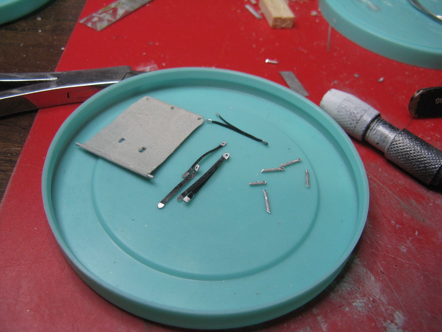
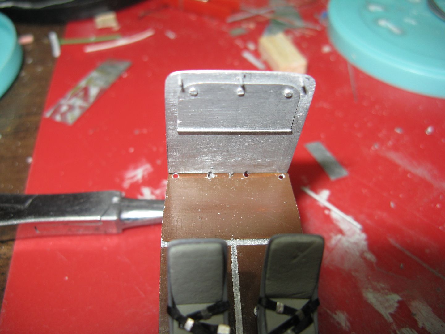
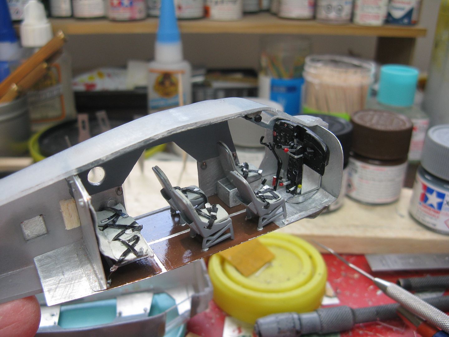
I have the rear seat and seat belts made and here is the motley collection of parts to prove it.
The hammock seat across the rear has space for three people, four if they're little and one doesn't mind riding without a seat belt.
There's a single belt on either side, with two double belts that make up the three places. The belts were made from masking tape with the buckles from beverage can.
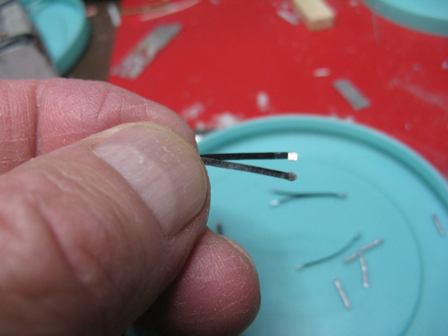
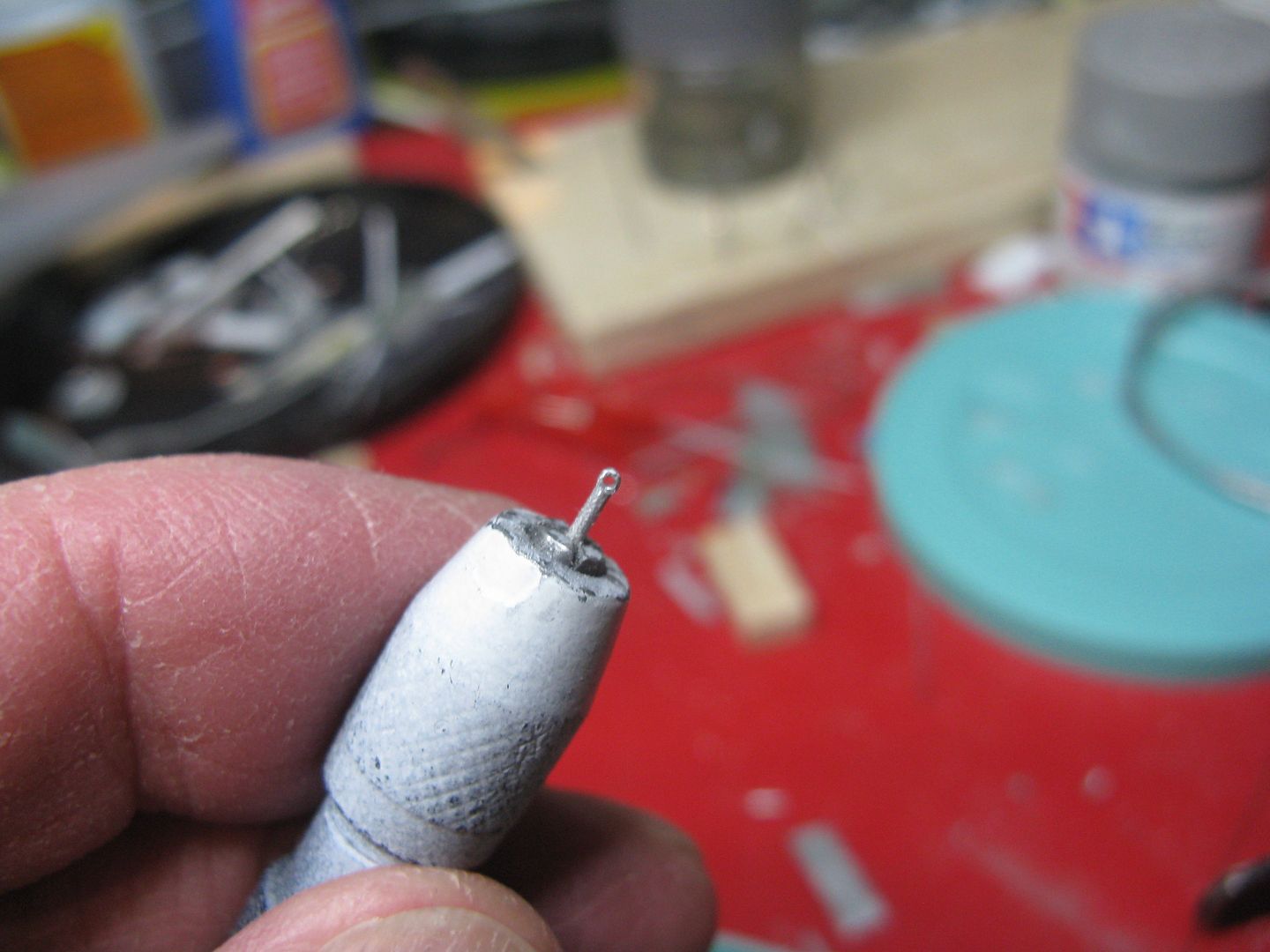
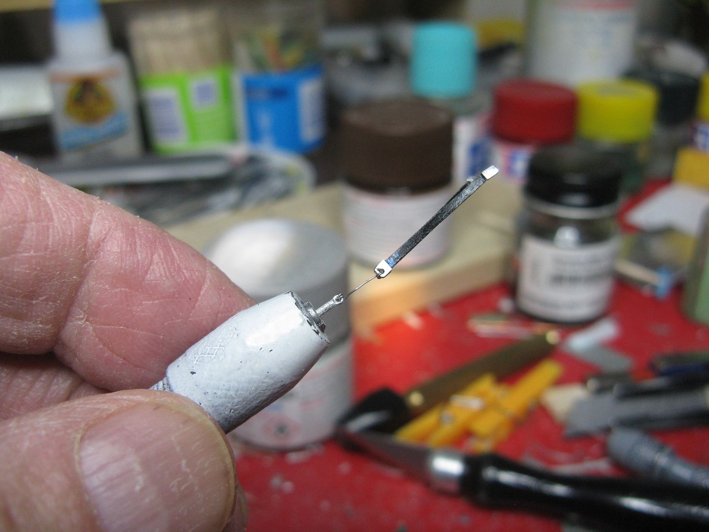
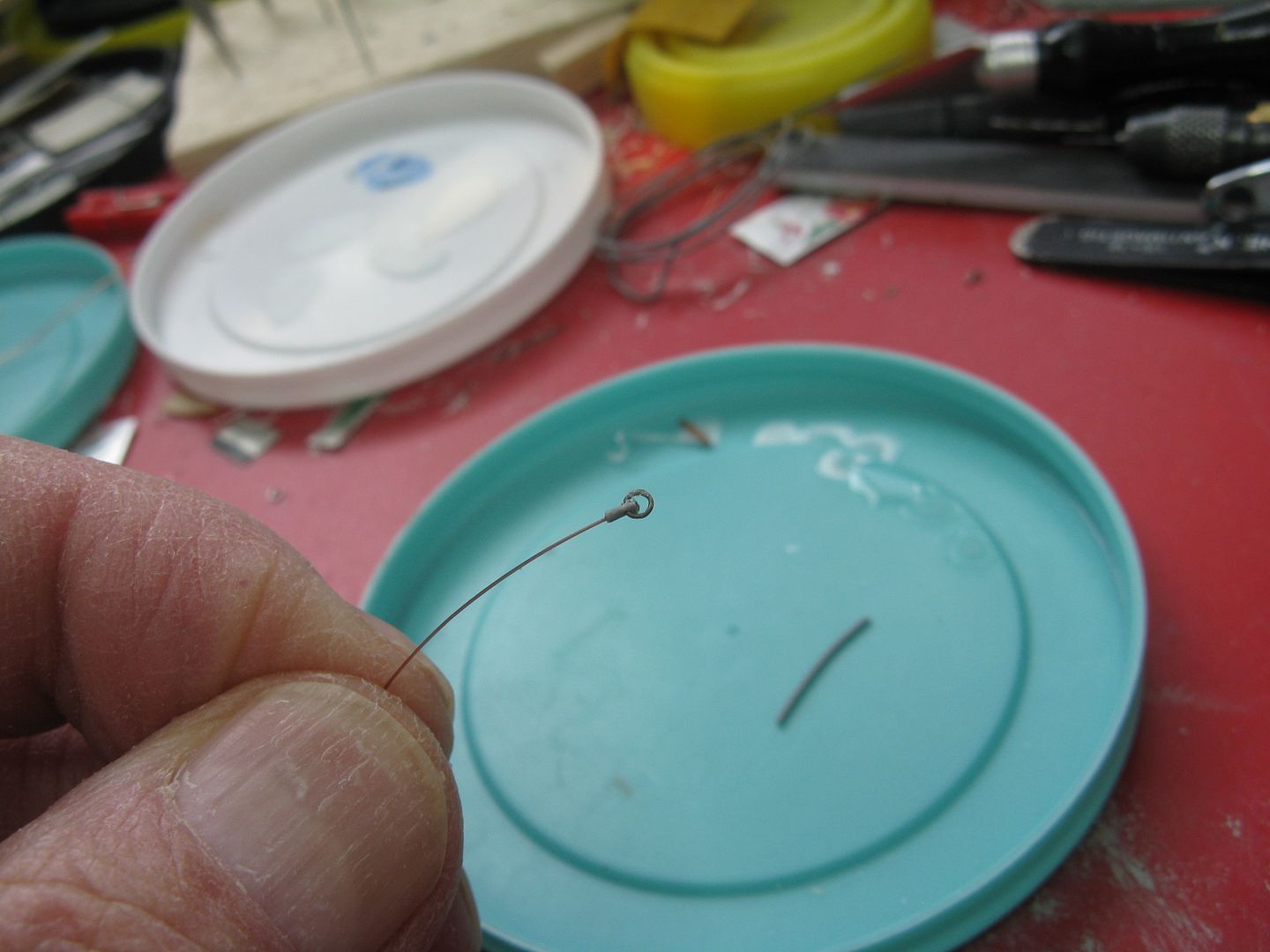
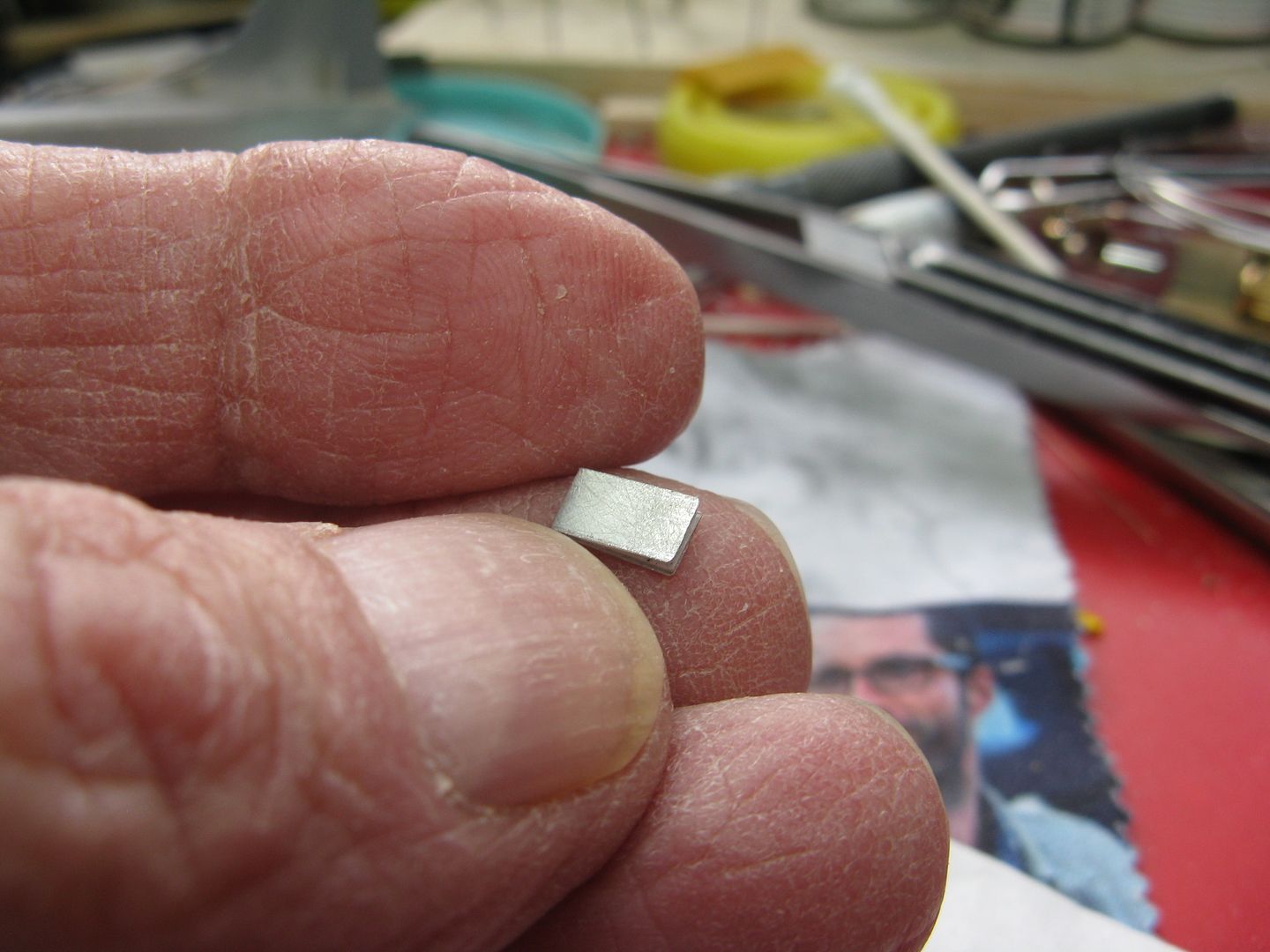
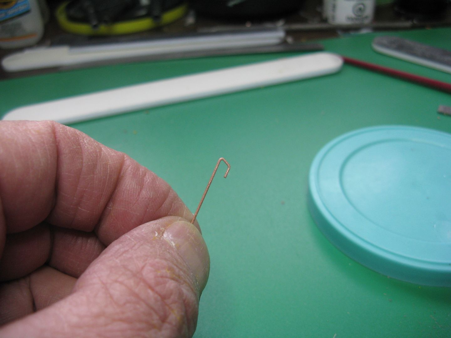
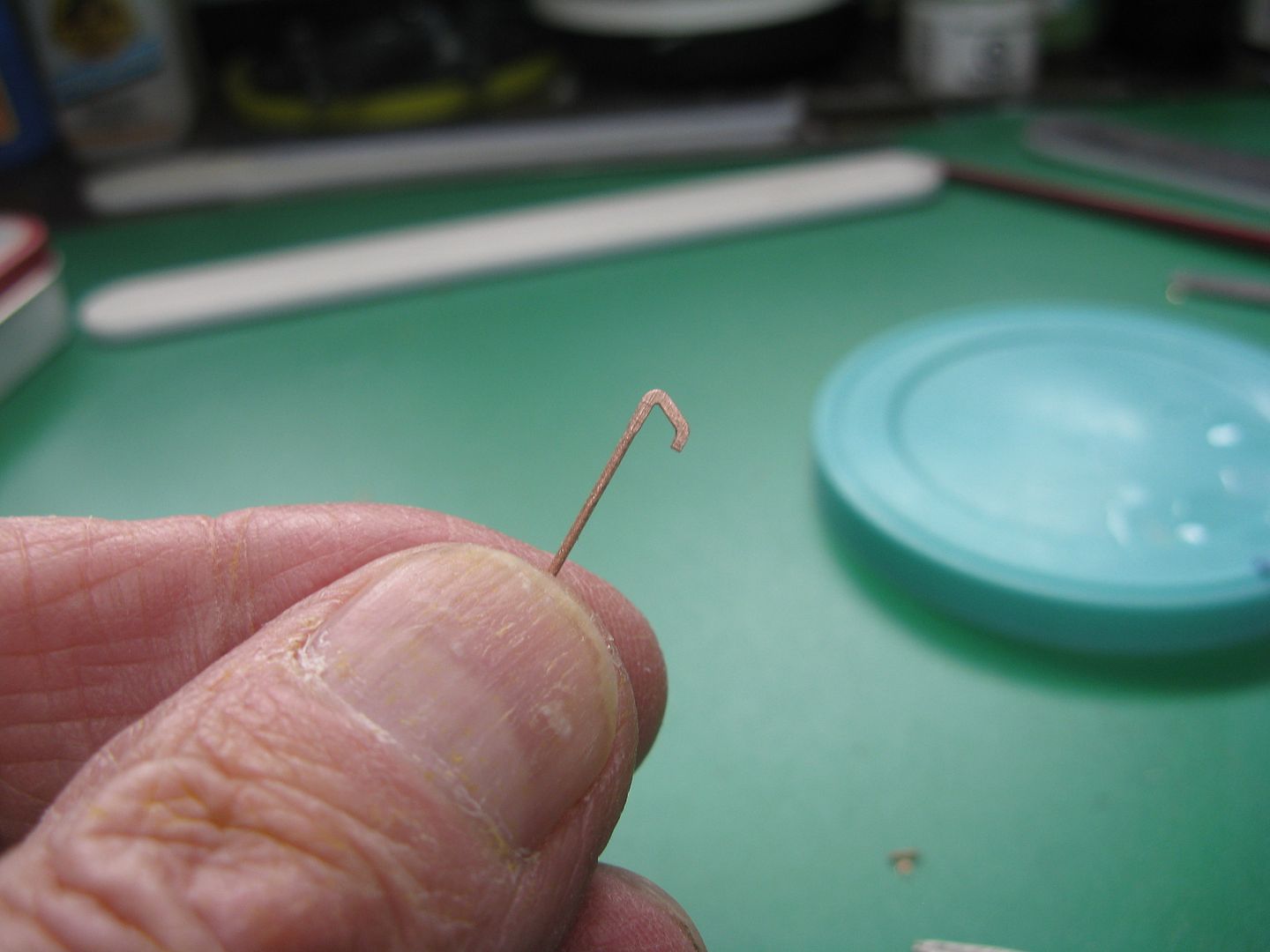
They are attached to the floor via a tie down and a short length of cable. To make the tie down I squeezed a short length of wire with a pair of pliers and drilled a hole in the squoze part and firkytoodled it to shape.
Then attached a bit of wire to the end of the belt itself...
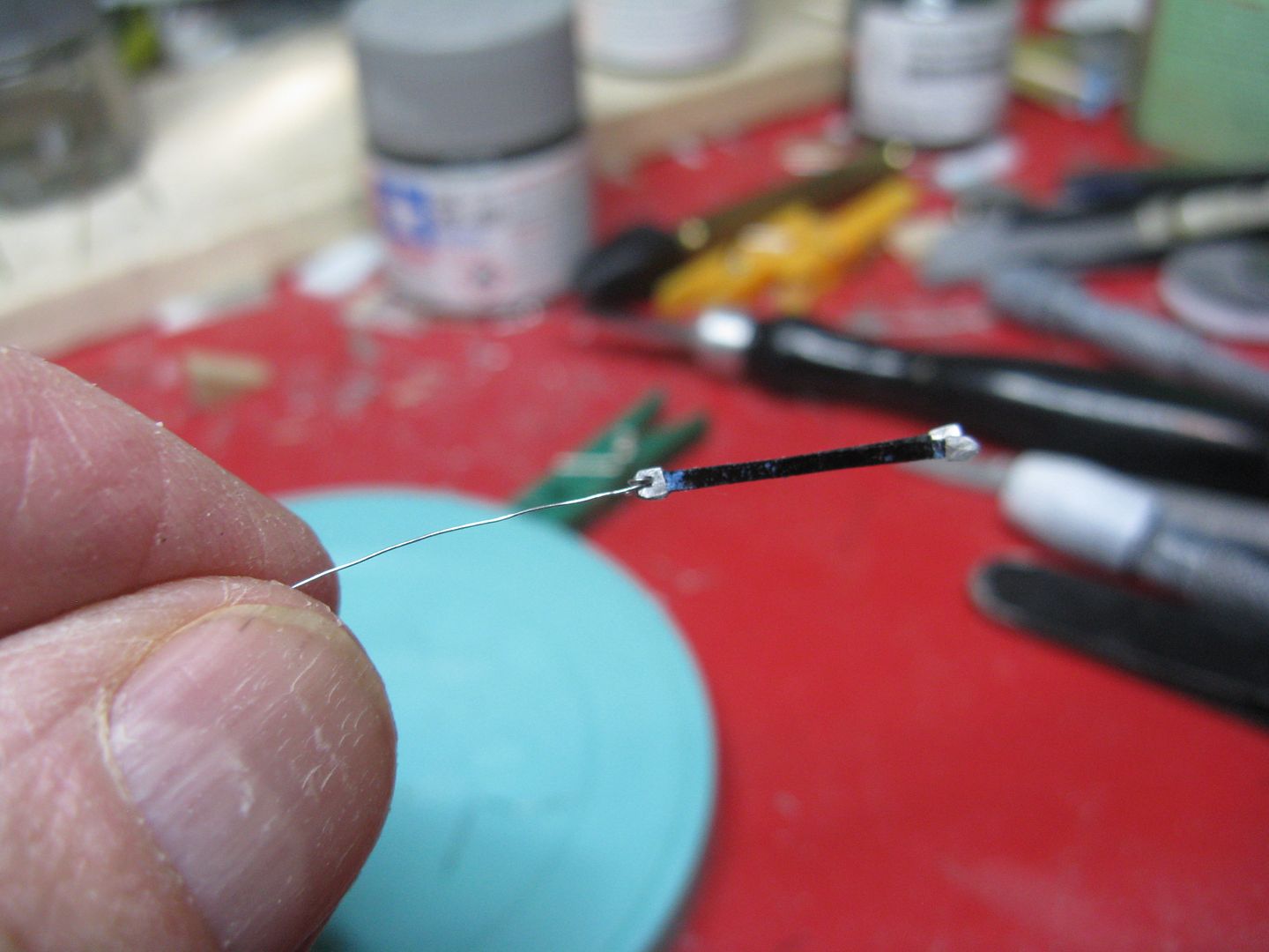
...And attached the wire to the hole in my tie down. One down, three to go.
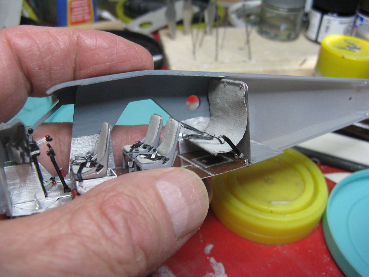
The hammock seat I made from a couple of folds of Kim Wipe, cut to size, painted a pleasing shade of grey, with two holes for the center seat belts to pass through, and with that pole from the preceding post glued to the lower end.
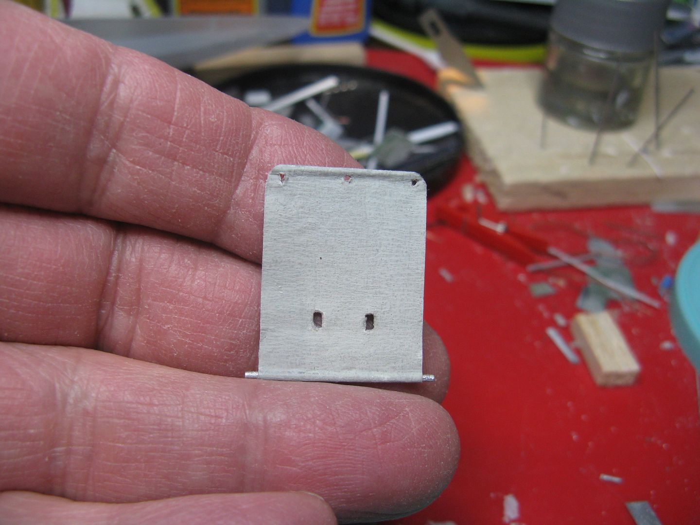
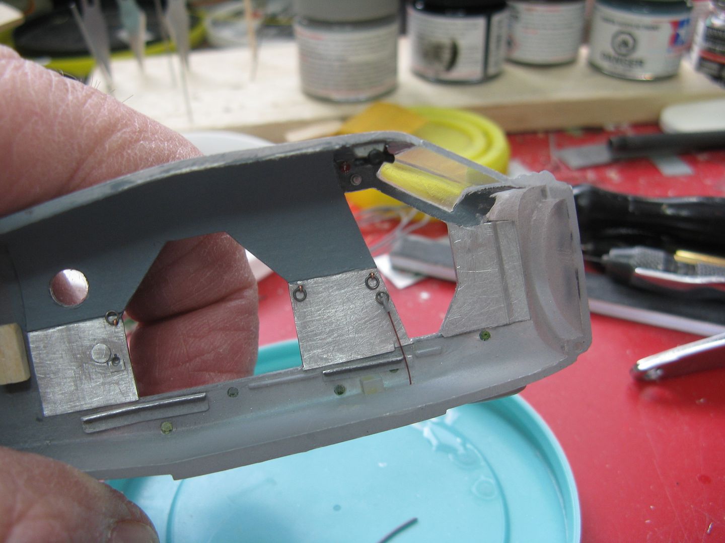
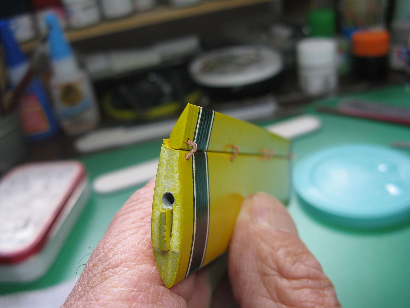
The top end of the seat hung from the rear bulkhead, near the cabin roof. I cut three holes in the top of seat...
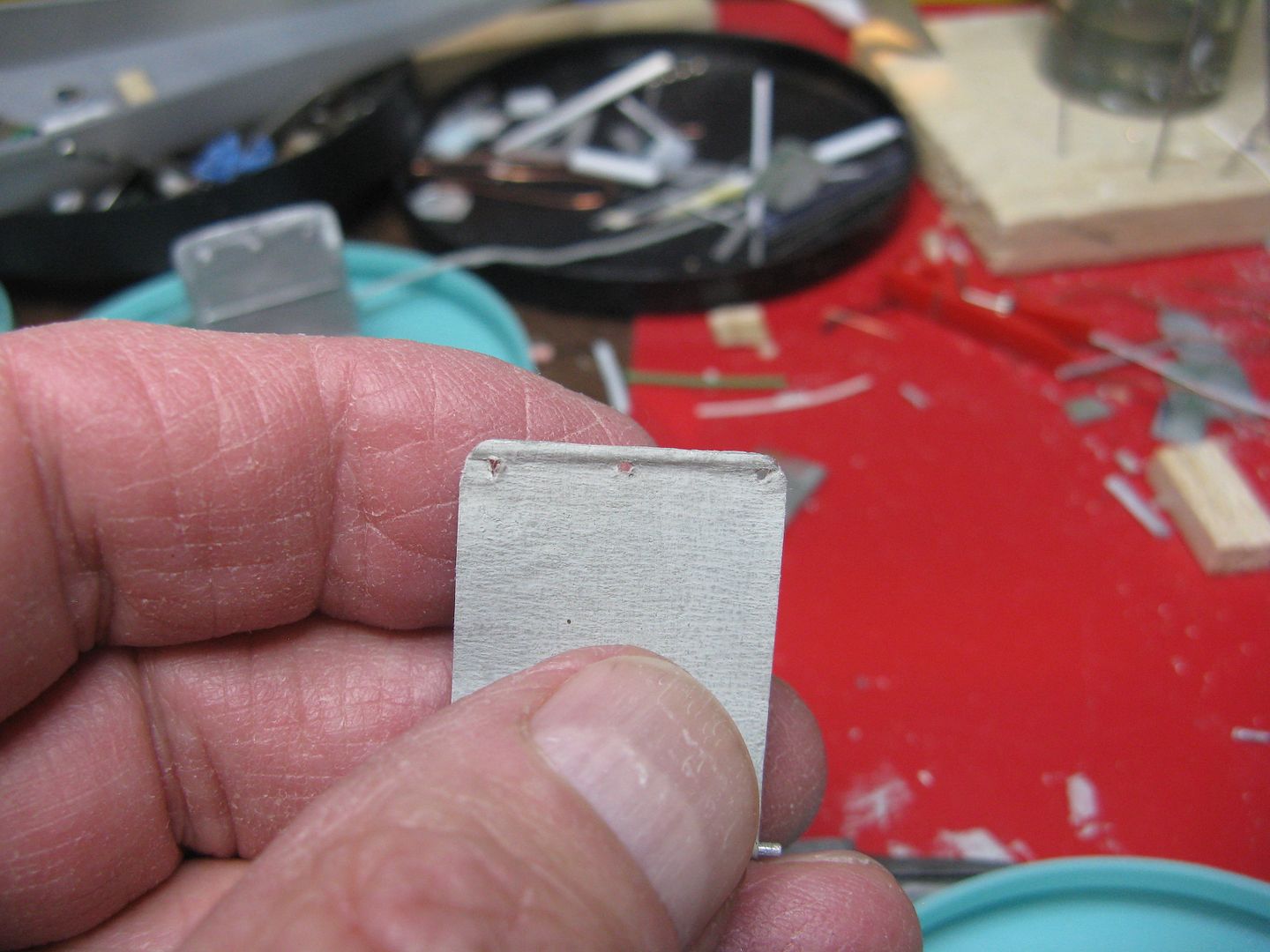
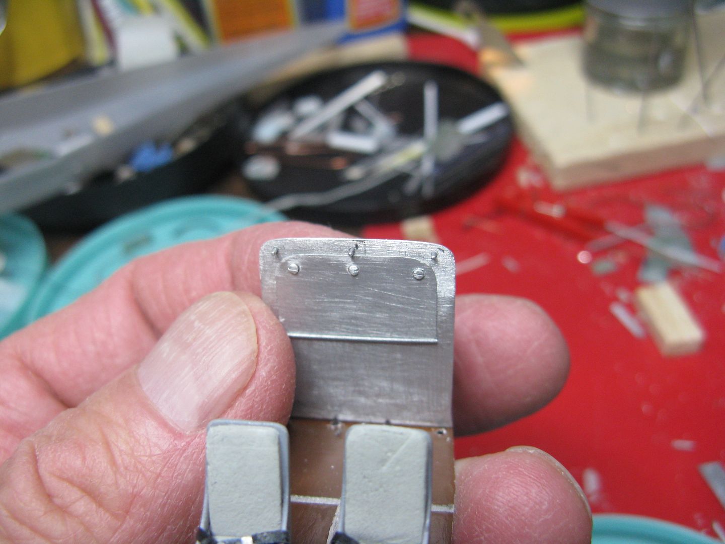
...That corresponds to the three 'hooks' on the rear bulkhead.
The tie downs will be fixed in these four holes in the floor.
I had on hand a paper template of the cabin headliner, so it was a simple matter to cut out a copy.
Before gluing it in place, it behooves one to make some supports for it. A few bits of wood, sanded to shape and glued in place, will do nicely.
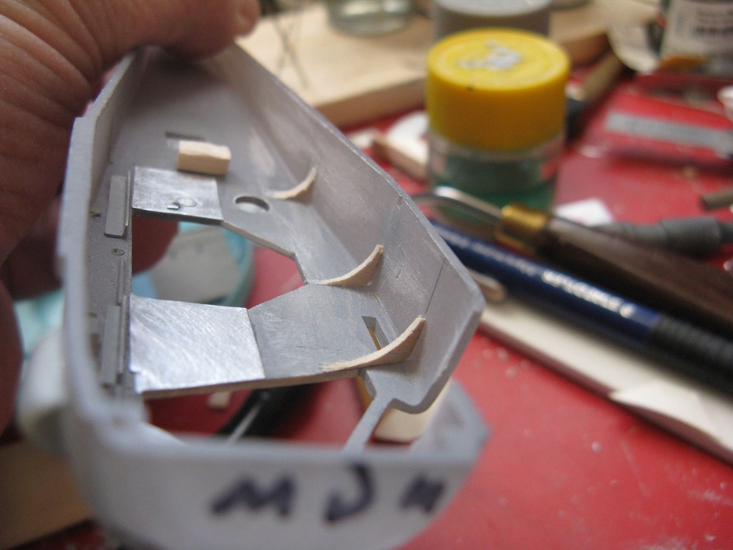
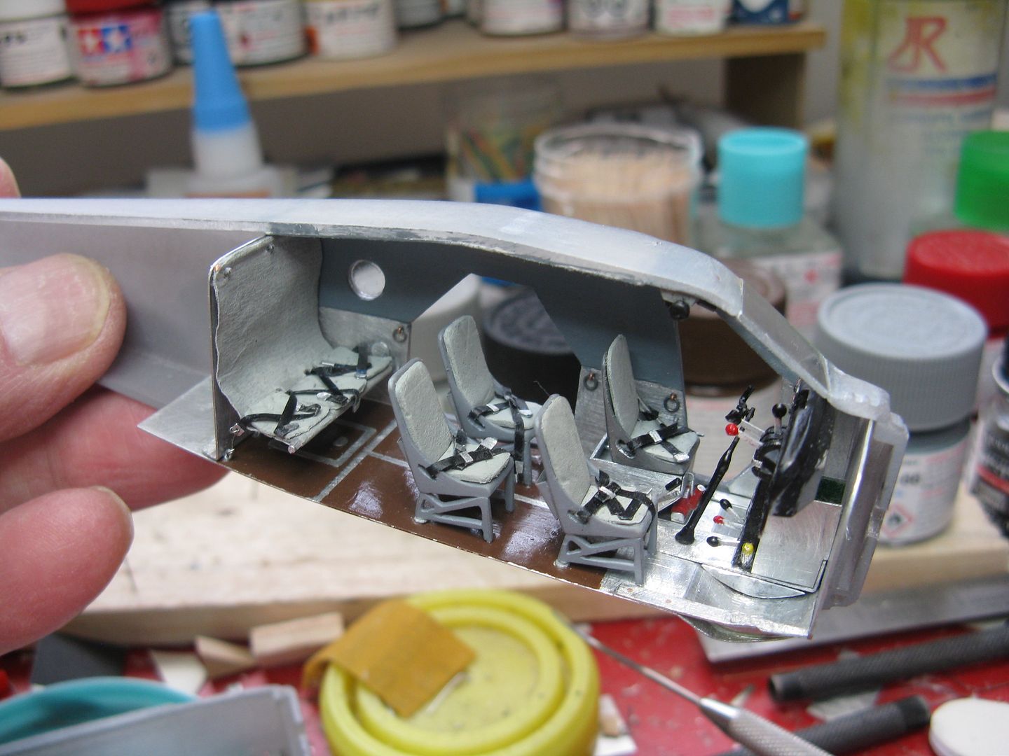
Minus the paint, here is what it looks like glued in place and trimmed to fit.
Add a lick of paint and dry fit the seat, and there she be.
I have the interior nearly completed, actually. I made six little cargo tie down rings from scrap wire, and a UV instrument spotlight. Right now I'm in the process of forming the windshield halves, using a wooden jiglet and some kind of clear acrylic material. This involves heat, supplied by the kitchen stove. It can also lead to an outburst of "What are you doing up there, I smell burning plastic" from Her Indoors, when the heat is a little too high. I have to make the rudder and elevator trim console for the cockpit roof, and that'll be about it. Then on to the final assembly.

Yeah I'd ride in the back back...
Thanks for the kind comments guys.
<<Absolutely Outstanding, Suh!>>
Why thank you, Suh!
John I can't remember what that stuff was called, could have been that. I do believe it was a kind of honeycomb, with metal on the bottom.
Since I had removed the windshield halves I needed to make two new ones. I used this little jiglet...
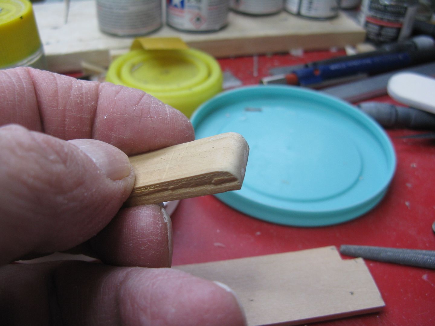
...Which is simply a piece of cedar shim, sanded to shape. To make a half, take a piece of clear acrylic and clamp it between the jiglet and another slice of shim, then hold it over the opening of a boiling kettle.*
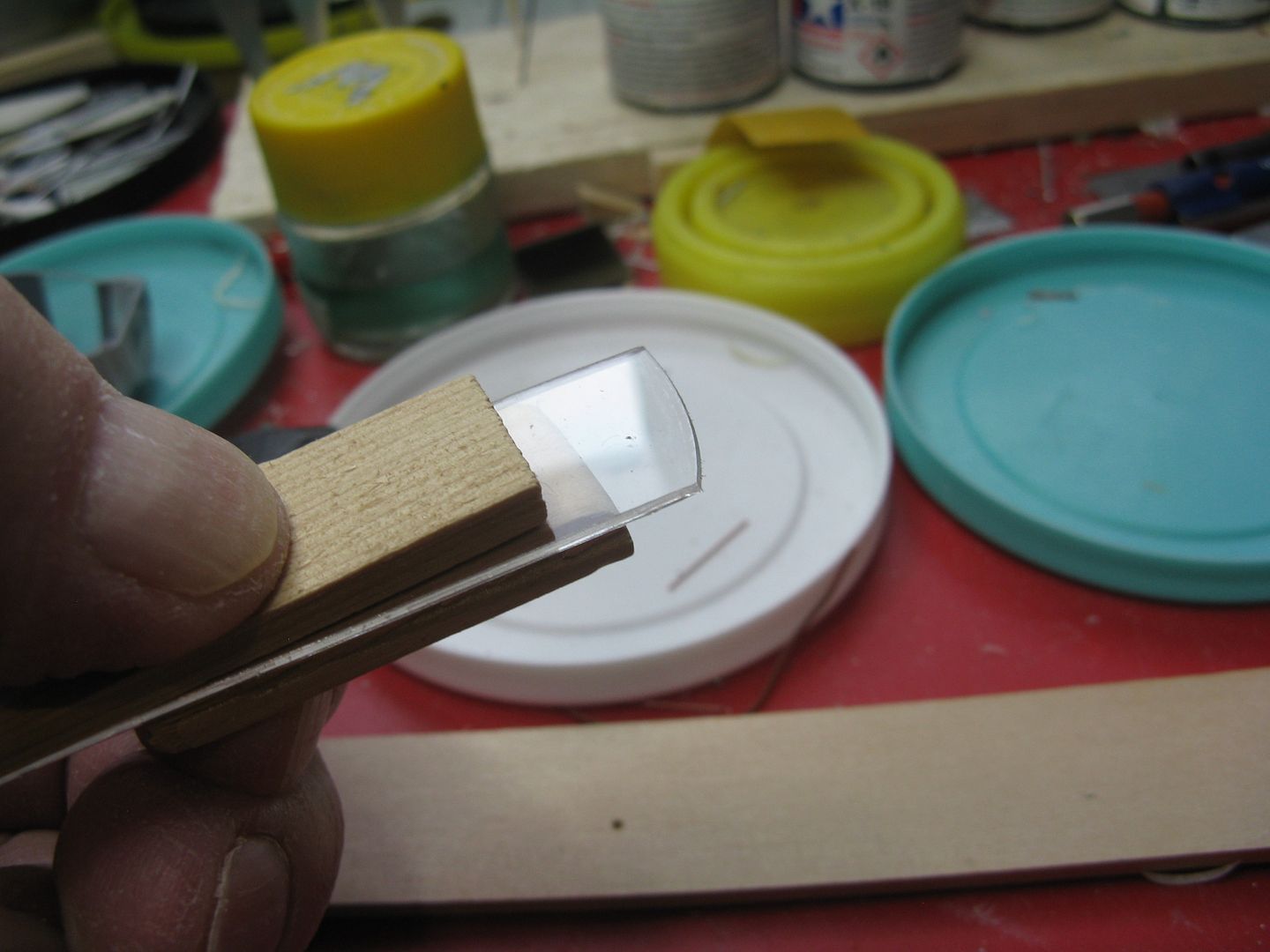
The acrylic will soften and once it's soft, bend it around the curved edge of the jiglet and hold it under cold running water. It'll harden in that shape, and with any luck at all after a prodigious amount of firkytoodling it'll fit properly.
* I had tried softening the material using the heat from the counter cooktop, which led to the aforementioned "Whaddya doing up there, is that burning plastic I smell?" war cry. Also, I was using acrylic that was too thin. I had tried to use some .020 thickness, but it 'cured' too fast. Then I had an epiphany. I had a couple of little screw-top containers of fleur de sel, with the top being made from, you guessed it, clear acrylic, that measured .040 thickness. One try using dry heat and it clouded when bent, so out came the kettle. Eureka! Perfect windshield halves in two tries, one right, one left. As a bonus, it polishes nicely. I have always used Meguiar's Mirror Glaze as a clear plastic polish but I can't find it anymore, so now I use another Meguiar's product, PlastX, what I call son of Mirror Glaze.
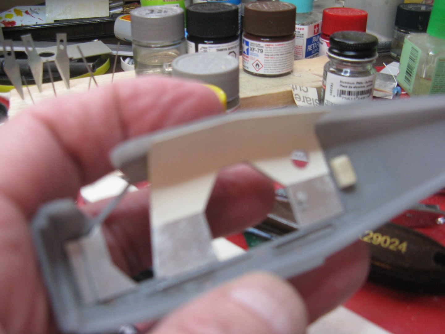
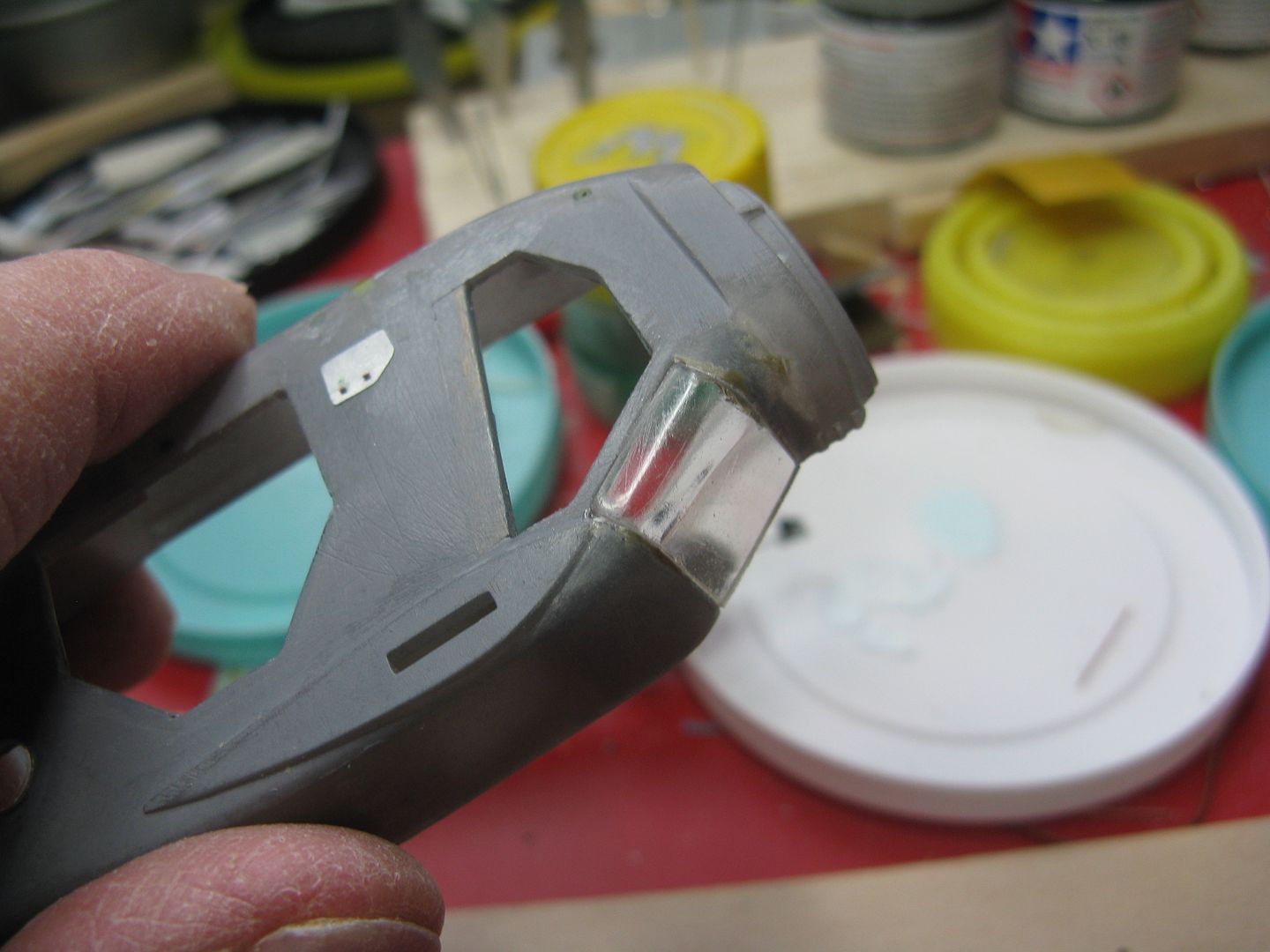
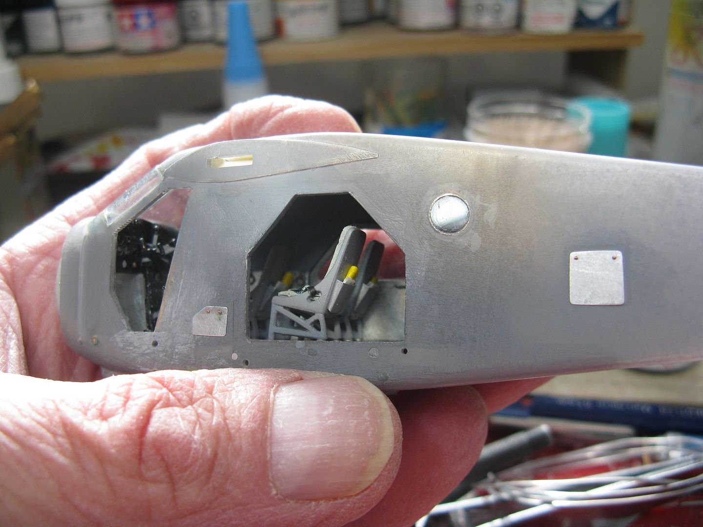
I made a little console for the elevator and rudder trim wheels, for mounting on the cockpit roof. The console is a bit of scrap plastic and the rubber wheels were pounded out of some plastic sheet using a Micro Mark punch, and painted black.
And here it is in place. This airplane had tip tanks. The little red dot in the wing root is the tip tank selector, left side only. The tip tanks drained into the front underfloor tank, and I seem to recall there was a restriction on their use. This in addition to being a right pita to fill. The metal thingy immediately below it is one of the cockpit fresh air vents. There's another on the other side.
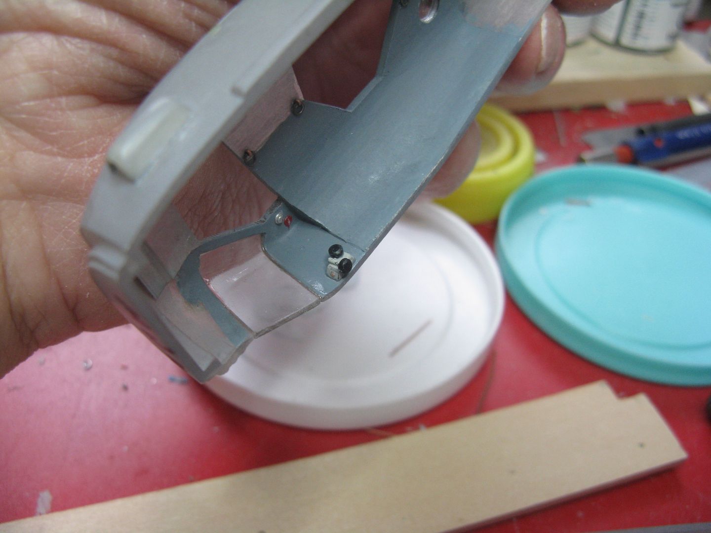
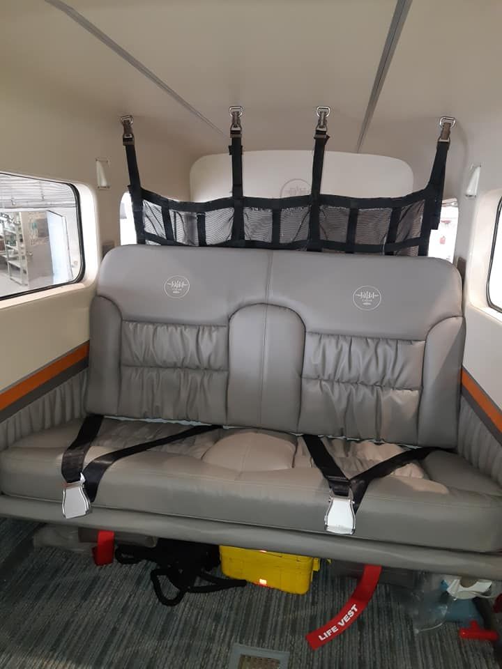
Here's a pic of the back seat of a Beaver that has undergone the Full Cleveland retrofit. That includes a cabin extension, the Alaska door and new seats, among other things. It even has little opera sidelights, by the looks of it. Rich Corinthian leather! Won't nobody be carrying fish in this sucker no more.
<<Absolutely Outstanding, Suh!>>
Why thank you, Suh!
John I can't remember what that stuff was called, could have been that. I do believe it was a kind of honeycomb, with metal on the bottom.
Since I had removed the windshield halves I needed to make two new ones. I used this little jiglet...
...Which is simply a piece of cedar shim, sanded to shape. To make a half, take a piece of clear acrylic and clamp it between the jiglet and another slice of shim, then hold it over the opening of a boiling kettle.*
The acrylic will soften and once it's soft, bend it around the curved edge of the jiglet and hold it under cold running water. It'll harden in that shape, and with any luck at all after a prodigious amount of firkytoodling it'll fit properly.
* I had tried softening the material using the heat from the counter cooktop, which led to the aforementioned "Whaddya doing up there, is that burning plastic I smell?" war cry. Also, I was using acrylic that was too thin. I had tried to use some .020 thickness, but it 'cured' too fast. Then I had an epiphany. I had a couple of little screw-top containers of fleur de sel, with the top being made from, you guessed it, clear acrylic, that measured .040 thickness. One try using dry heat and it clouded when bent, so out came the kettle. Eureka! Perfect windshield halves in two tries, one right, one left. As a bonus, it polishes nicely. I have always used Meguiar's Mirror Glaze as a clear plastic polish but I can't find it anymore, so now I use another Meguiar's product, PlastX, what I call son of Mirror Glaze.
I made a little console for the elevator and rudder trim wheels, for mounting on the cockpit roof. The console is a bit of scrap plastic and the rubber wheels were pounded out of some plastic sheet using a Micro Mark punch, and painted black.
And here it is in place. This airplane had tip tanks. The little red dot in the wing root is the tip tank selector, left side only. The tip tanks drained into the front underfloor tank, and I seem to recall there was a restriction on their use. This in addition to being a right pita to fill. The metal thingy immediately below it is one of the cockpit fresh air vents. There's another on the other side.
Here's a pic of the back seat of a Beaver that has undergone the Full Cleveland retrofit. That includes a cabin extension, the Alaska door and new seats, among other things. It even has little opera sidelights, by the looks of it. Rich Corinthian leather! Won't nobody be carrying fish in this sucker no more.
chrispisme
Well-known member
Beautiful work James!
On the picture of the real(full size) beaver it looks as though the centre of the seat folds down as an armrest or cup holder kind of thing?
Beautiful interior...not what I’m used to seeing in those planes!
Have you built a long cabin conversion yet?
On the picture of the real(full size) beaver it looks as though the centre of the seat folds down as an armrest or cup holder kind of thing?
Beautiful interior...not what I’m used to seeing in those planes!
Have you built a long cabin conversion yet?
Excellent Step by Step James, thank you for this.
nice job!
nice job!
Thanks fells.
Chris I think you're right about the arm rest and cup holders. That pic is from Neil Aird's site, it's s/n 1000, CF-PCG. I doubt it'll ever carry another load of freight. I've not built one with the cabin extension. Kenmore windows instead of the porthole, yes.
I got the fuselage buttoned up on this one, but first a couple of small details. I added a water rudder pull-up cable...
...And dry fitted it here. This is the position where it was hooked once the water rudders were retracted. Another position was on the lower left instrument panel, below the fuel selector. This one's easier to build and install once the floats are installed.
I epoxied the cabin into the l/h fuselage half, making sure the rear seat lower support lined up with the hole in the r/h half...
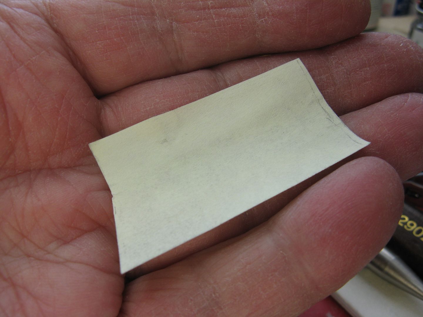
...Then added a few bits of wire insulation squeezed flat and painted yellow to represent the life vest pouches and a couple of tiny folds of paper to represent the barf bags to the seat back pockets, and glued both halves together.
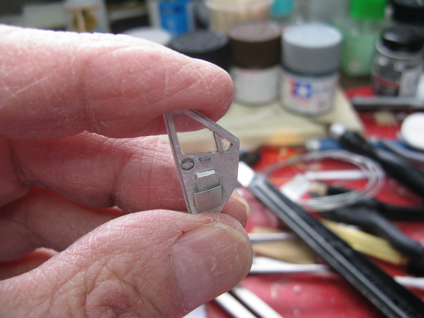
A bit of scrap beverage can cut to shape and folded over for the aircraft journey log book cover...
...Will fit into the left front door pocket.
Since I had previously cut the bottom off the rudder, I made a new fillet with a bit of cedar shim and firkytoodled it to shape...
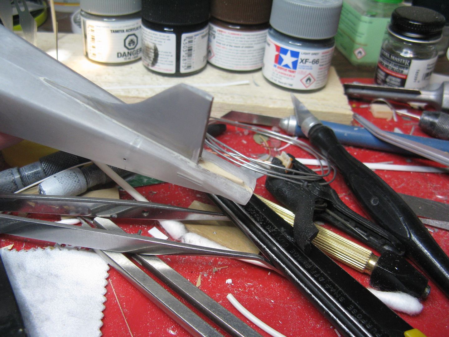
...And while I was at it, why not make a rudder trim actuator from a bit of squeezed wire and attach it in the correct location?
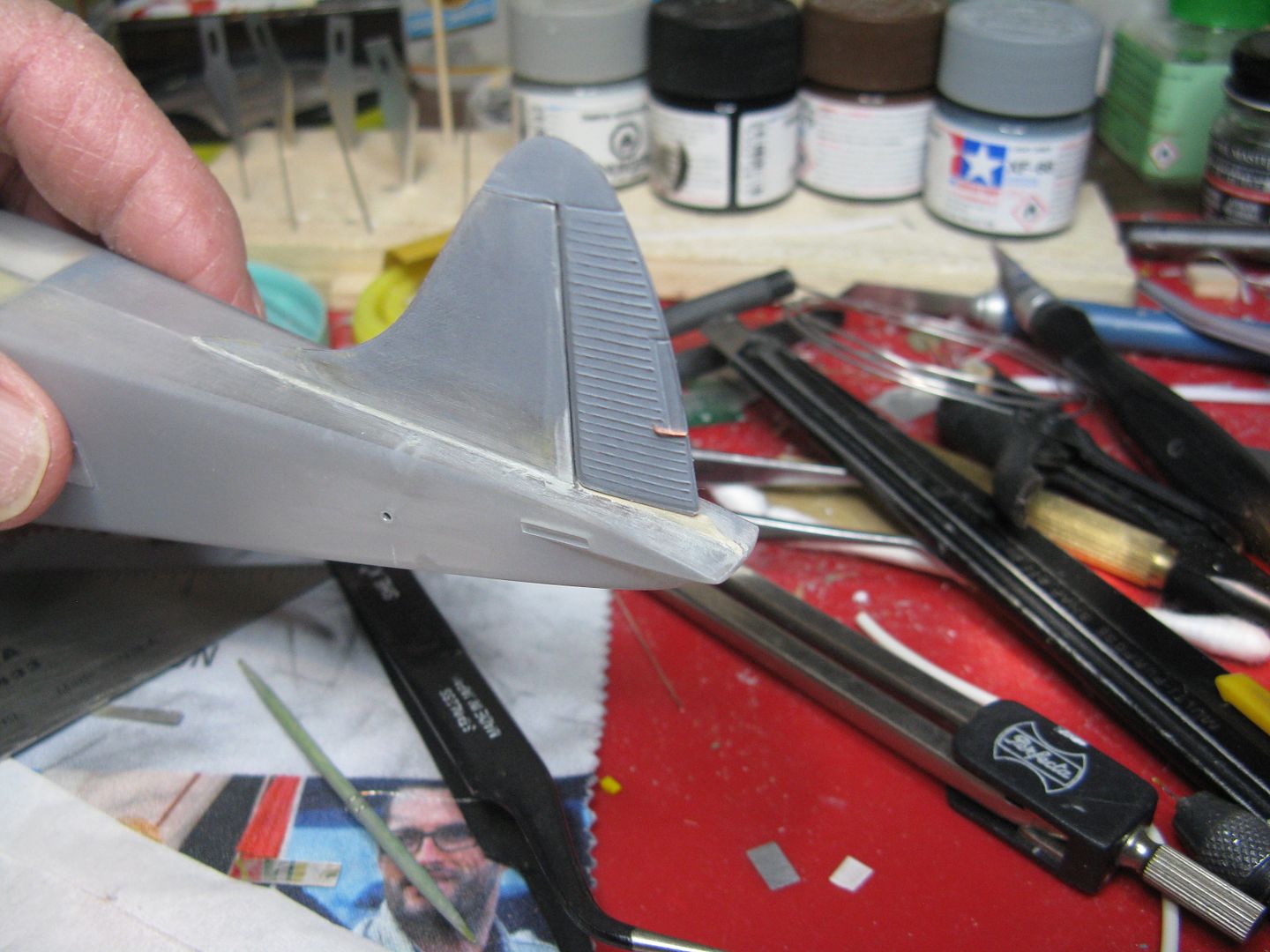
Some final sanding and this one will be ready for priming.
Chris I think you're right about the arm rest and cup holders. That pic is from Neil Aird's site, it's s/n 1000, CF-PCG. I doubt it'll ever carry another load of freight. I've not built one with the cabin extension. Kenmore windows instead of the porthole, yes.
I got the fuselage buttoned up on this one, but first a couple of small details. I added a water rudder pull-up cable...
...And dry fitted it here. This is the position where it was hooked once the water rudders were retracted. Another position was on the lower left instrument panel, below the fuel selector. This one's easier to build and install once the floats are installed.
I epoxied the cabin into the l/h fuselage half, making sure the rear seat lower support lined up with the hole in the r/h half...
...Then added a few bits of wire insulation squeezed flat and painted yellow to represent the life vest pouches and a couple of tiny folds of paper to represent the barf bags to the seat back pockets, and glued both halves together.
A bit of scrap beverage can cut to shape and folded over for the aircraft journey log book cover...
...Will fit into the left front door pocket.
Since I had previously cut the bottom off the rudder, I made a new fillet with a bit of cedar shim and firkytoodled it to shape...
...And while I was at it, why not make a rudder trim actuator from a bit of squeezed wire and attach it in the correct location?
Some final sanding and this one will be ready for priming.
chrispisme
Well-known member
I can almost smell the avgas now! Beautiful job James!
Did I ever tell you I worked on Beaver 01 once upon a time? Back in the ‘70’s when it was in Norcanair livery and I was a green young apprenticeling..
Don’t remember what I did but remember when it flew out to go to a museum as a display piece
Did I ever tell you I worked on Beaver 01 once upon a time? Back in the ‘70’s when it was in Norcanair livery and I was a green young apprenticeling..
Don’t remember what I did but remember when it flew out to go to a museum as a display piece
Stunning...
Thanks fellas.
Chris that airplane is in the Aviation Museum in Ottawa now, still in Norcanair livery. Last time I saw it was 2003, and if you sniffed hard enough there was still a whiff of rotten fish around.
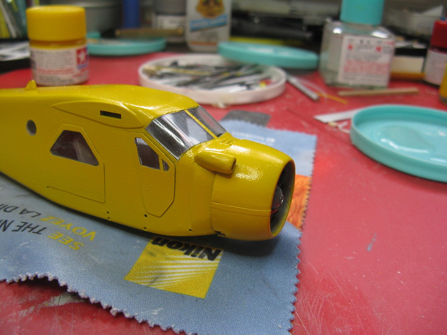
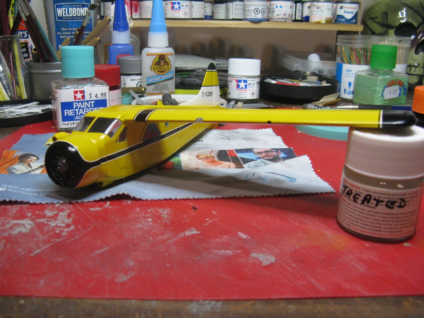
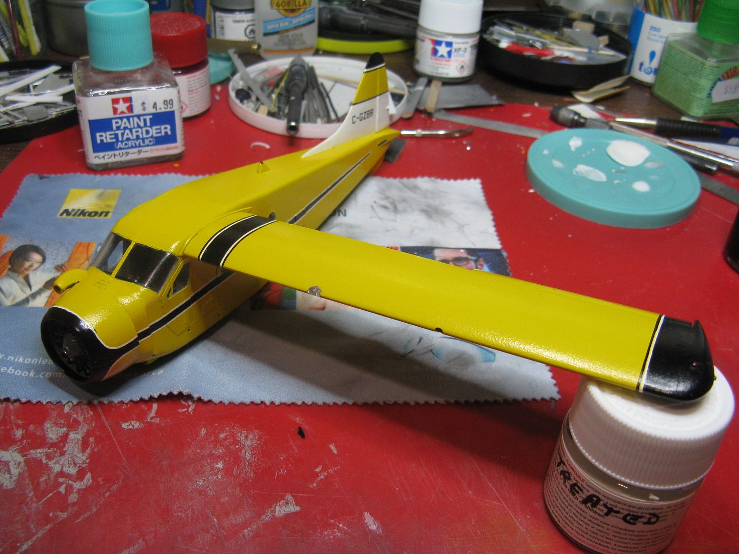
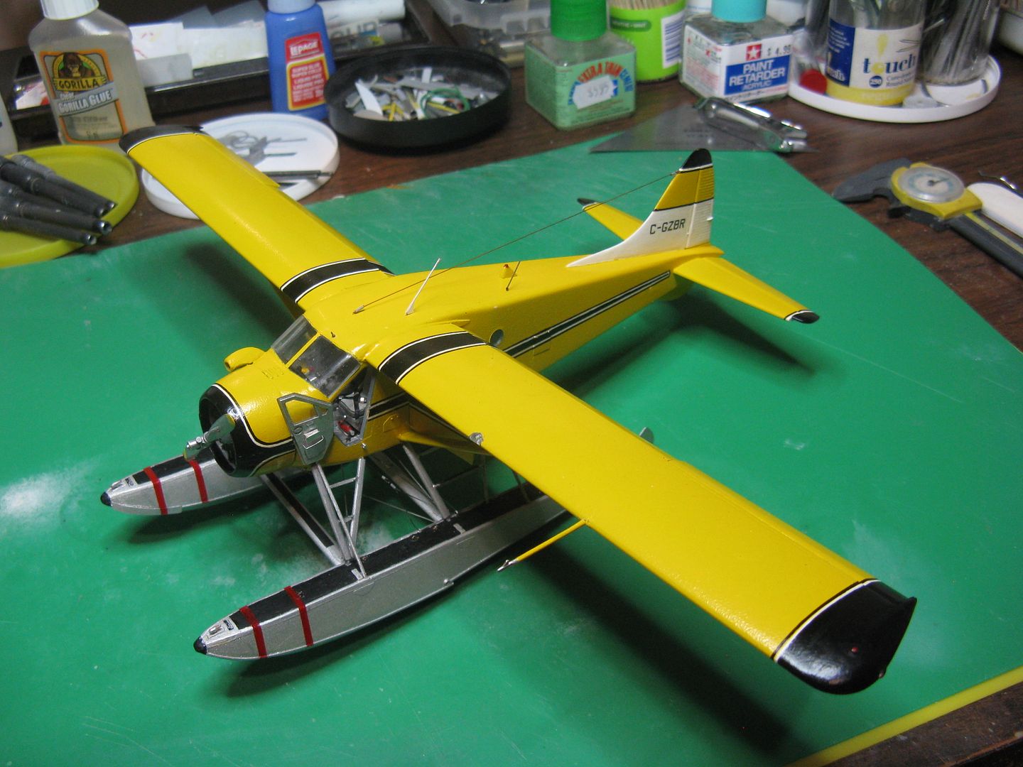
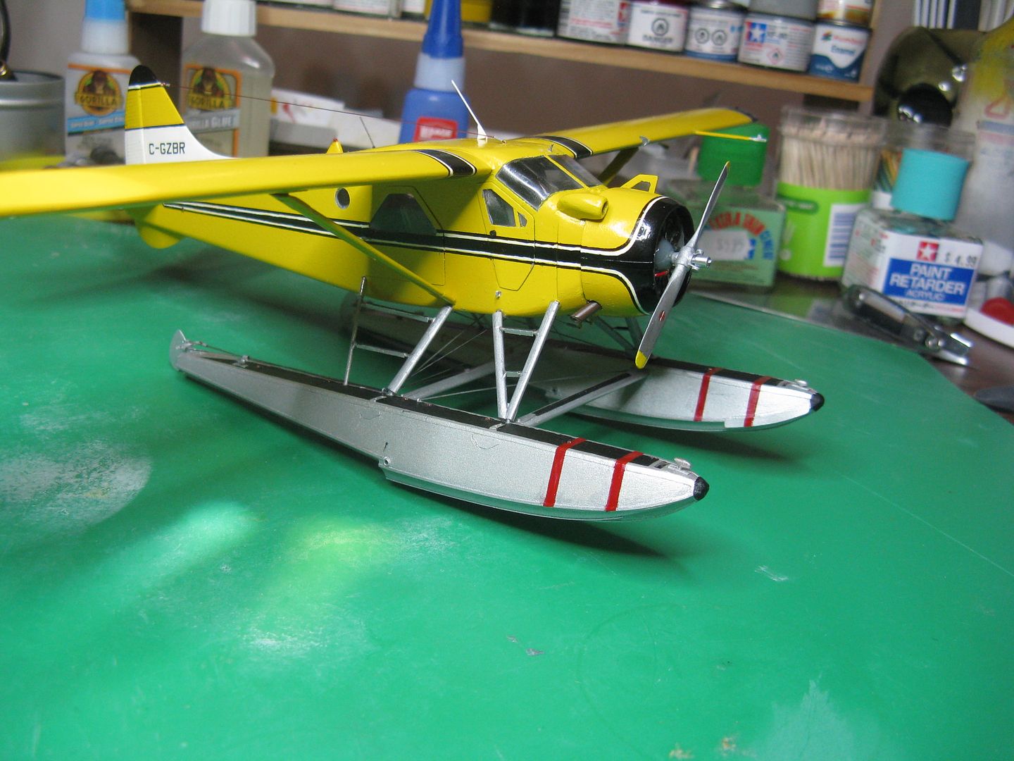
Anyway, got a bit of colour on this thing. Four mist coats plus a wet topcoat of Tamiya yellow over a base of flat aluminum.
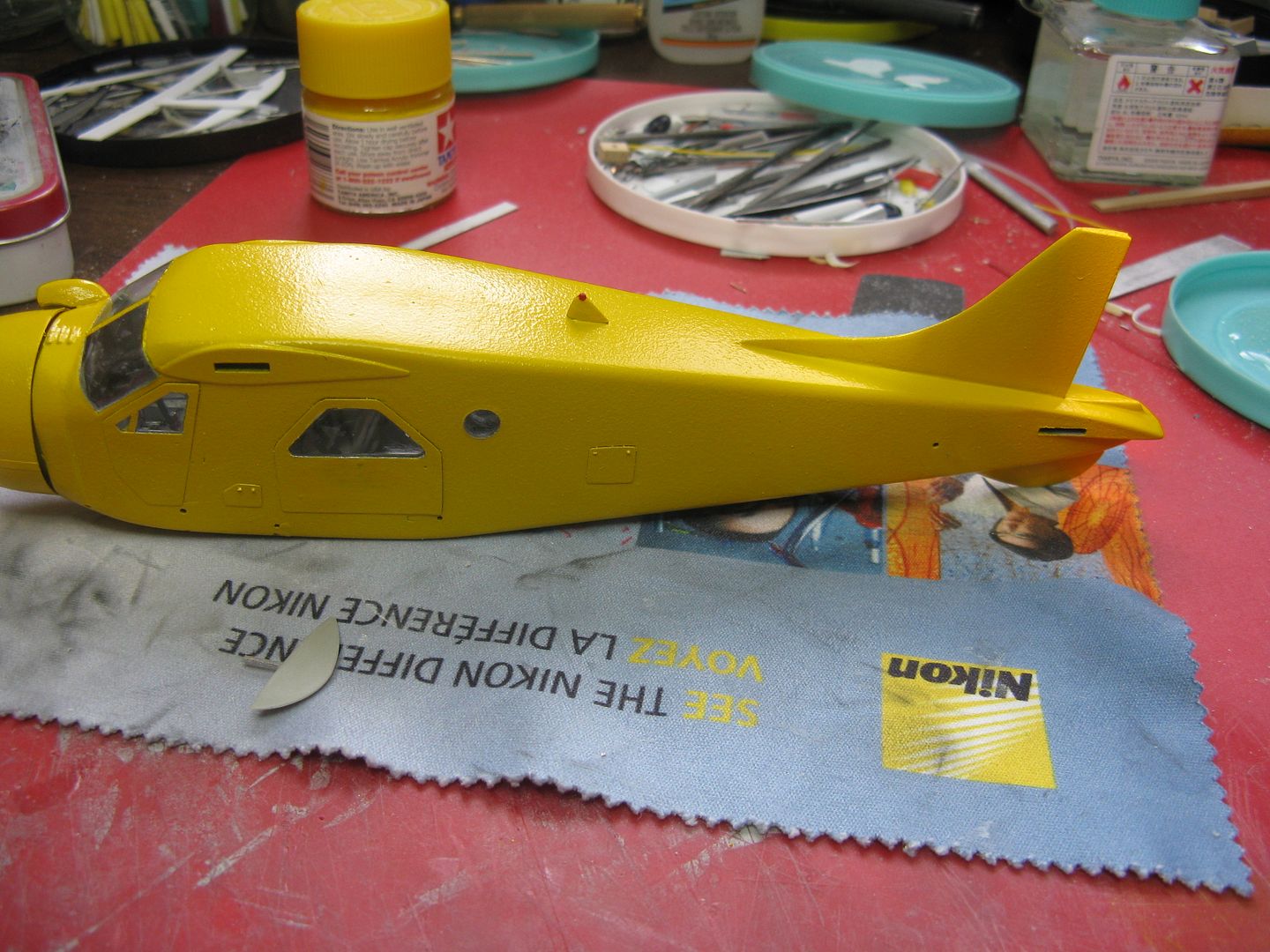
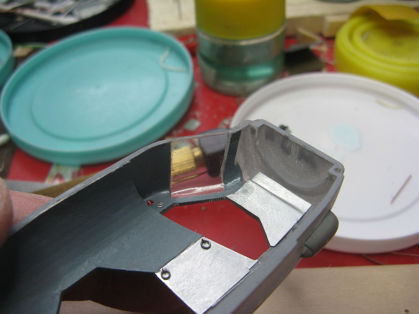
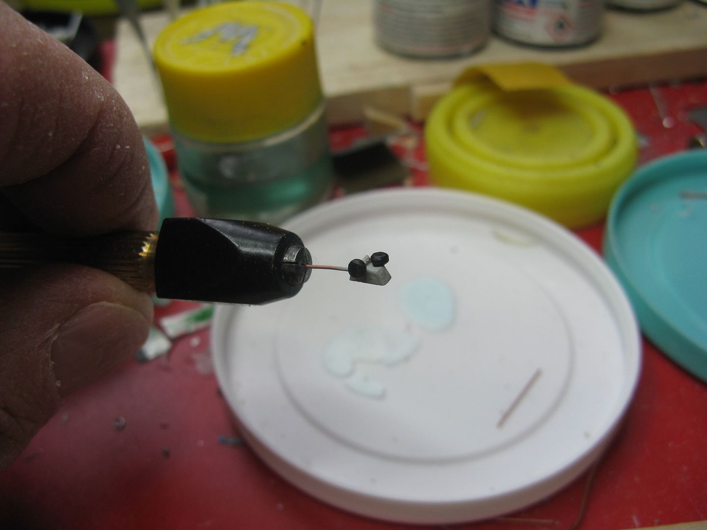
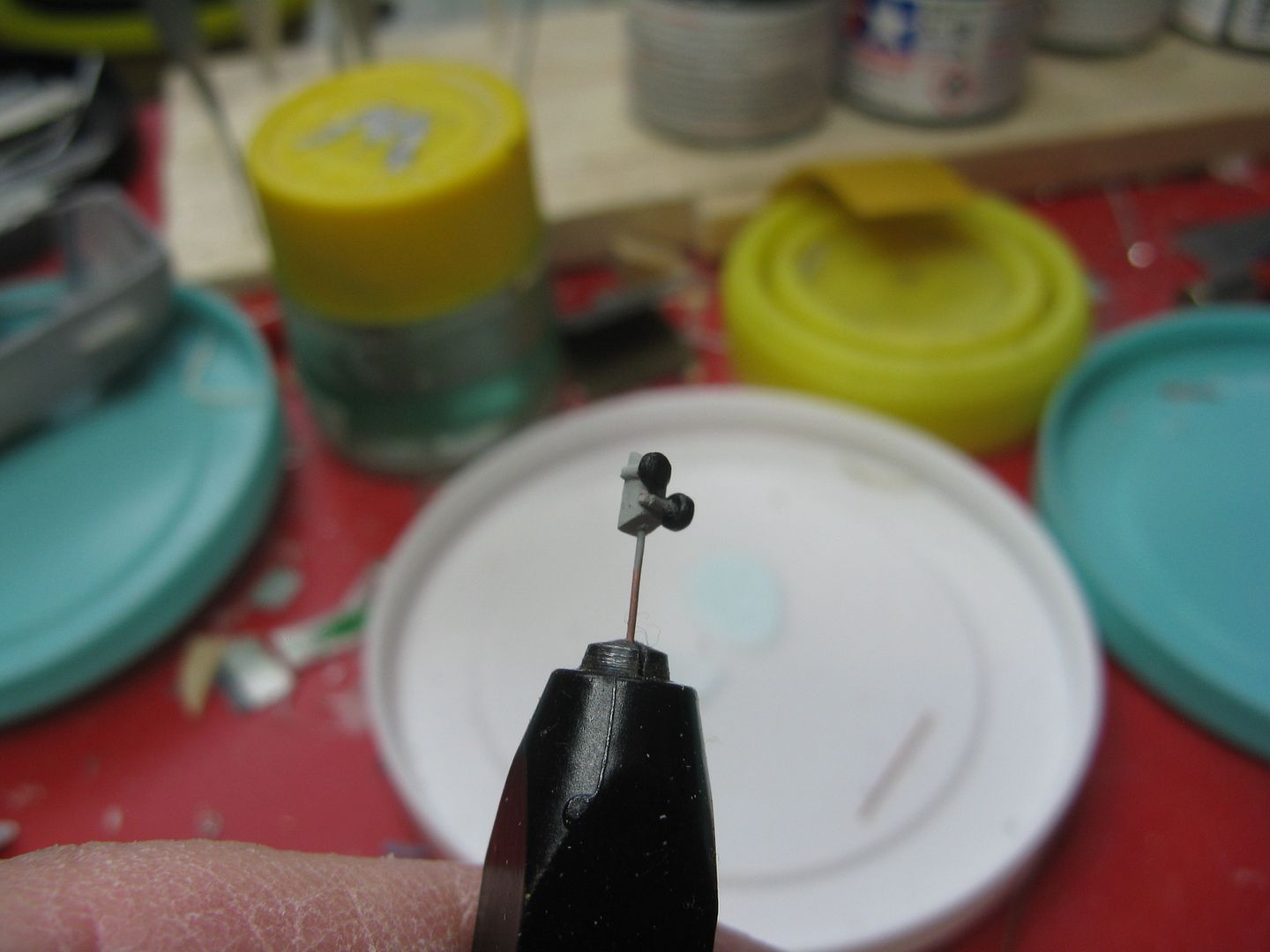
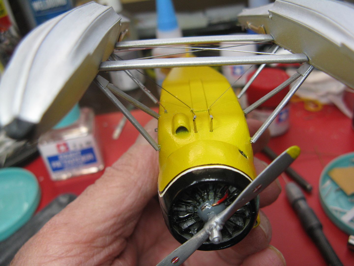
The rotating beacon is home made from a bit of plastic and wire, with a drop of epoxy as a lens. This airplane has what I call the desert kit, with the carb air scoop mounted on the upper right. The scoop I firkytoodled from a tiny block of wood.
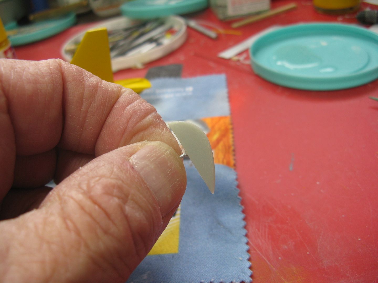
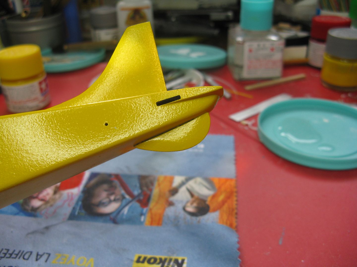
The kit ventral fin - aka the dock knocker - is the correct shape but too small by several sizes, so I made a new one from a scrap of plastic.
On to the trim. A pox upon the house of the idiot who came up with painted wing bands. Pestilence and famine to the bigger idiot who thought "Let's put pin striping around those wing bands." All of those lines have to be reproduced. I don't know how anyone else does it, but I lay down the main colour - in this case black - first. When that has dried, I lay a narrow line of masking tape beside it the width of the pinstripe. Then I carefully, make that very carefully, hand paint the pinstripe using the masking tape on one side and the paint ridge from the main colour instead of another line of masking tape. It works surprisingly well, but believe me it is a major pita particularly if your painting hand is like the Waco Kid's shooting hand in Blazing Saddles. With some minor corrections, it is coming along.
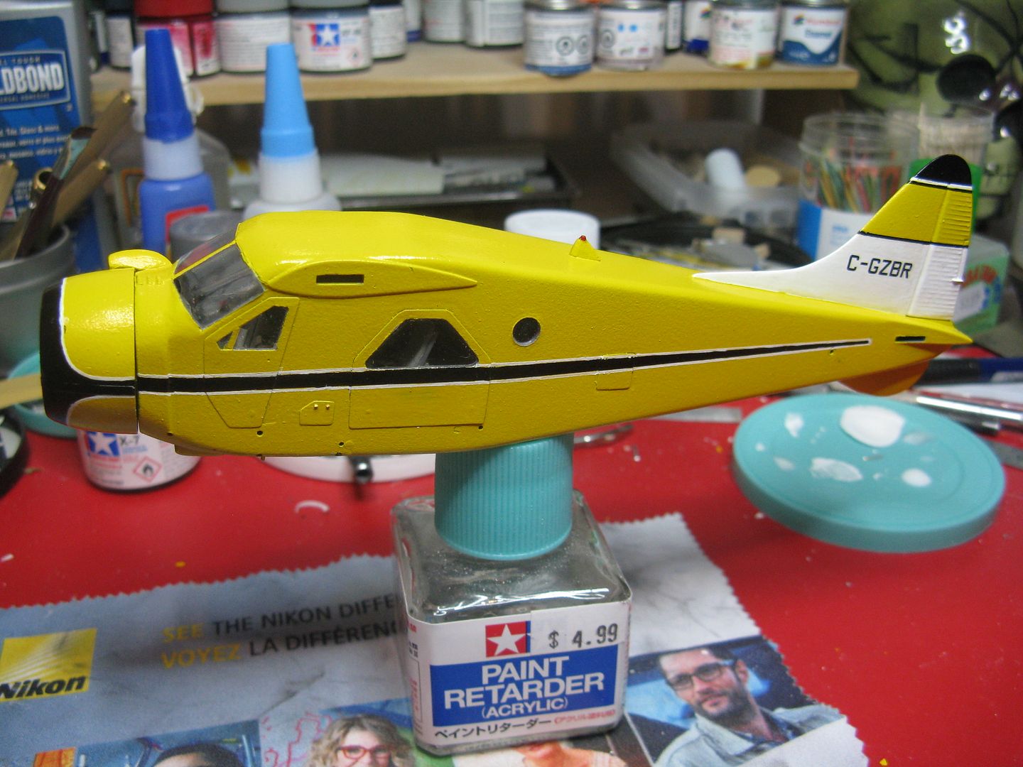
The little red dot on the wing tip there is the filler cap for the tip tank. The landing light I made by filing a half-round hole in the leading edge and lining it with chukw tape, then using a bit of polished aluminum wire as a bulb and filling the thing up with clear epoxy as a lens.
More pin striping coming up this week. Hopefully I'll have this thing mounted on her feet by next week. She'll be ready for float season Rich.
Chris that airplane is in the Aviation Museum in Ottawa now, still in Norcanair livery. Last time I saw it was 2003, and if you sniffed hard enough there was still a whiff of rotten fish around.
Anyway, got a bit of colour on this thing. Four mist coats plus a wet topcoat of Tamiya yellow over a base of flat aluminum.
The rotating beacon is home made from a bit of plastic and wire, with a drop of epoxy as a lens. This airplane has what I call the desert kit, with the carb air scoop mounted on the upper right. The scoop I firkytoodled from a tiny block of wood.
The kit ventral fin - aka the dock knocker - is the correct shape but too small by several sizes, so I made a new one from a scrap of plastic.
On to the trim. A pox upon the house of the idiot who came up with painted wing bands. Pestilence and famine to the bigger idiot who thought "Let's put pin striping around those wing bands." All of those lines have to be reproduced. I don't know how anyone else does it, but I lay down the main colour - in this case black - first. When that has dried, I lay a narrow line of masking tape beside it the width of the pinstripe. Then I carefully, make that very carefully, hand paint the pinstripe using the masking tape on one side and the paint ridge from the main colour instead of another line of masking tape. It works surprisingly well, but believe me it is a major pita particularly if your painting hand is like the Waco Kid's shooting hand in Blazing Saddles. With some minor corrections, it is coming along.
The little red dot on the wing tip there is the filler cap for the tip tank. The landing light I made by filing a half-round hole in the leading edge and lining it with chukw tape, then using a bit of polished aluminum wire as a bulb and filling the thing up with clear epoxy as a lens.
More pin striping coming up this week. Hopefully I'll have this thing mounted on her feet by next week. She'll be ready for float season Rich.
Sweeet!! 
phantom II
Master at Arms
Coming along very nicely
Cheers, Christian B)
Cheers, Christian B)
chrispisme
Well-known member
Looking good James
 :drinks
Duke Maddog
Well-known member
Wow, your pin-striping is incredible! You truly do have mad skills man! Way to go!
Thanks for the kind comments fellas, much appreciated.
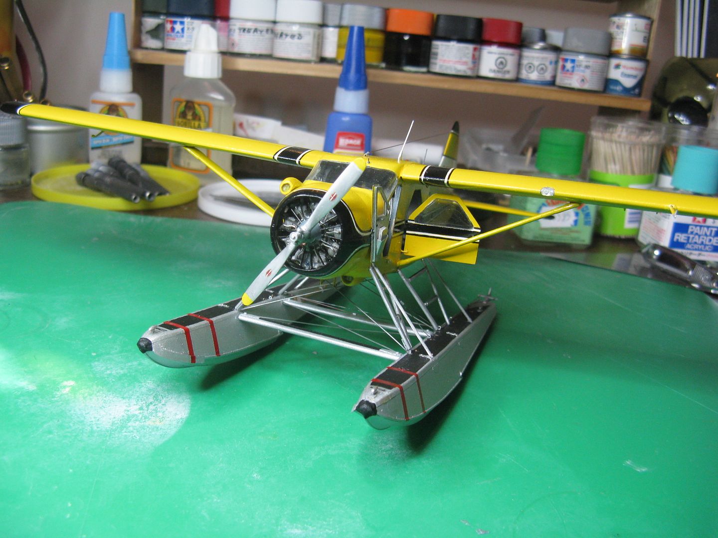
Well, stick a fork in this one. The rest of the assembly was pretty straightforward, consisted of adding the tail feathers and then the floats. After that was done glue on the wings and there you have it.
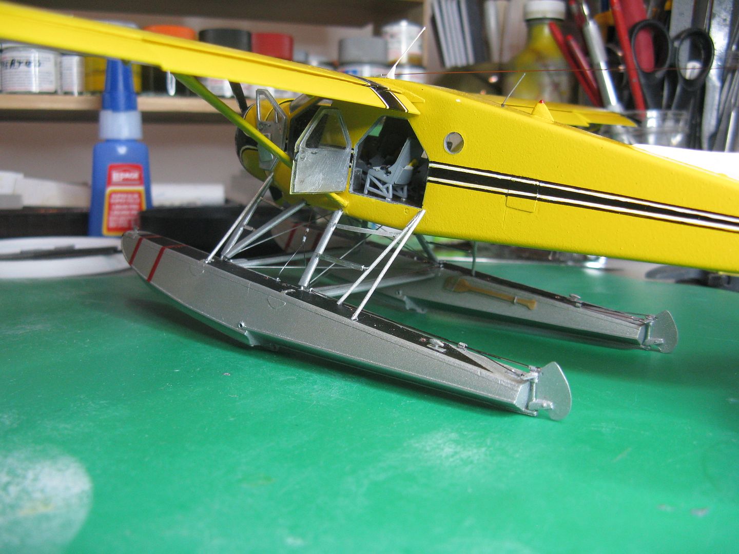
The floats went on well, but after I had it all squared away I didn't like the way it sat. I had used the kit float struts, but with the decks of the floats leveled, there was a very slight - but noticeable - nose down attitude. Nothing to do but very carefully remove the rear float struts and shorten them by 1/32' and Viola! problem solved. Next came connecting up the water rudder cables and installing the bracing wires. Here's the pull-up cable, that has both the cables from the water rudders attached to that nifty little dookickey I constructed some time ago, now glued to the left hand cockpit wall with the end of the cable protruding through a conduit in the cockpit floor.
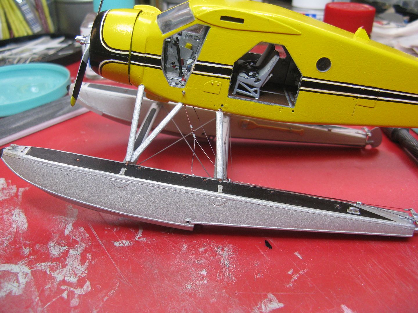
The main rudder directional control cables are attached to two little torque tubes that protrude through the bottom of the fuselage, with the upper ends attached to the rudder torque tube beneath the cockpit floor.
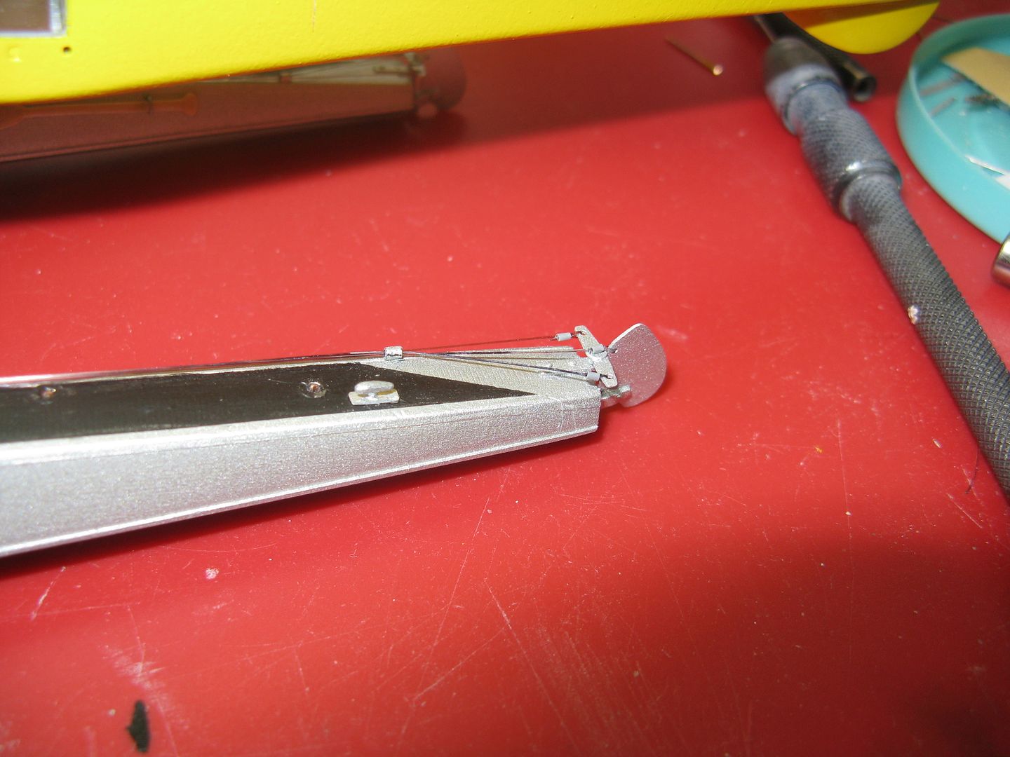
And here's everything attached to the proper holes in the water rudder tiller.
After adding the flaps and ailerons I decided to make some new flap hangers using the patented squeeze-a-bit-of-wire-to-the-correct-shape method, thusly. Take a piece of wire and bend it to the correct shape...
...Squeeze it flat with a pair of duck-billed pliers...
...Firkytoodle the heck out of it to correct the profile, and install in the existing holes in the underside of the wing.
There is a boarding 'ladder' that comprises an integral part of the rear float strut assembly. I used a bit of wire to simulate that as well as the ladder steps. This airplane has square pieces of angle metal attached to the steps to afford a more secure step, so I made some tiny angles using beverage can, and glued them to the wire steps. Neato! The other strut that runs from the top of the ladder to the outside deck angle of the left float only, is the rear strut of the canoe strut assembly. There is a forward strut also, running from just forward of the cockpit door sill to the outside edge of the float. You could carry a fairly large boat/canoe on the Beaver. The largest I've flown was 16' aluminum canoes. If you were carrying square stern boat, the square end always went forward. This avoided the large area of low pressure that would occur behind the square stern when airborne, thus affecting elevator effectiveness if the boat were carried in the conventional way. Strangest external load I ever carried was a dozen bed springs, six a side, attached to the float struts. They made an unholy whistling noise in cruise, fortunately it was a short trip.
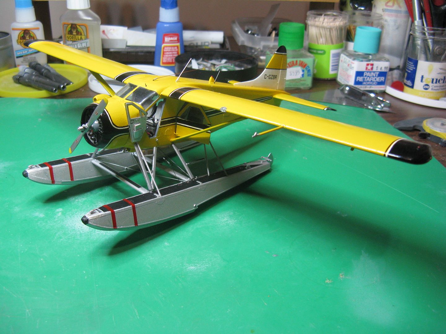
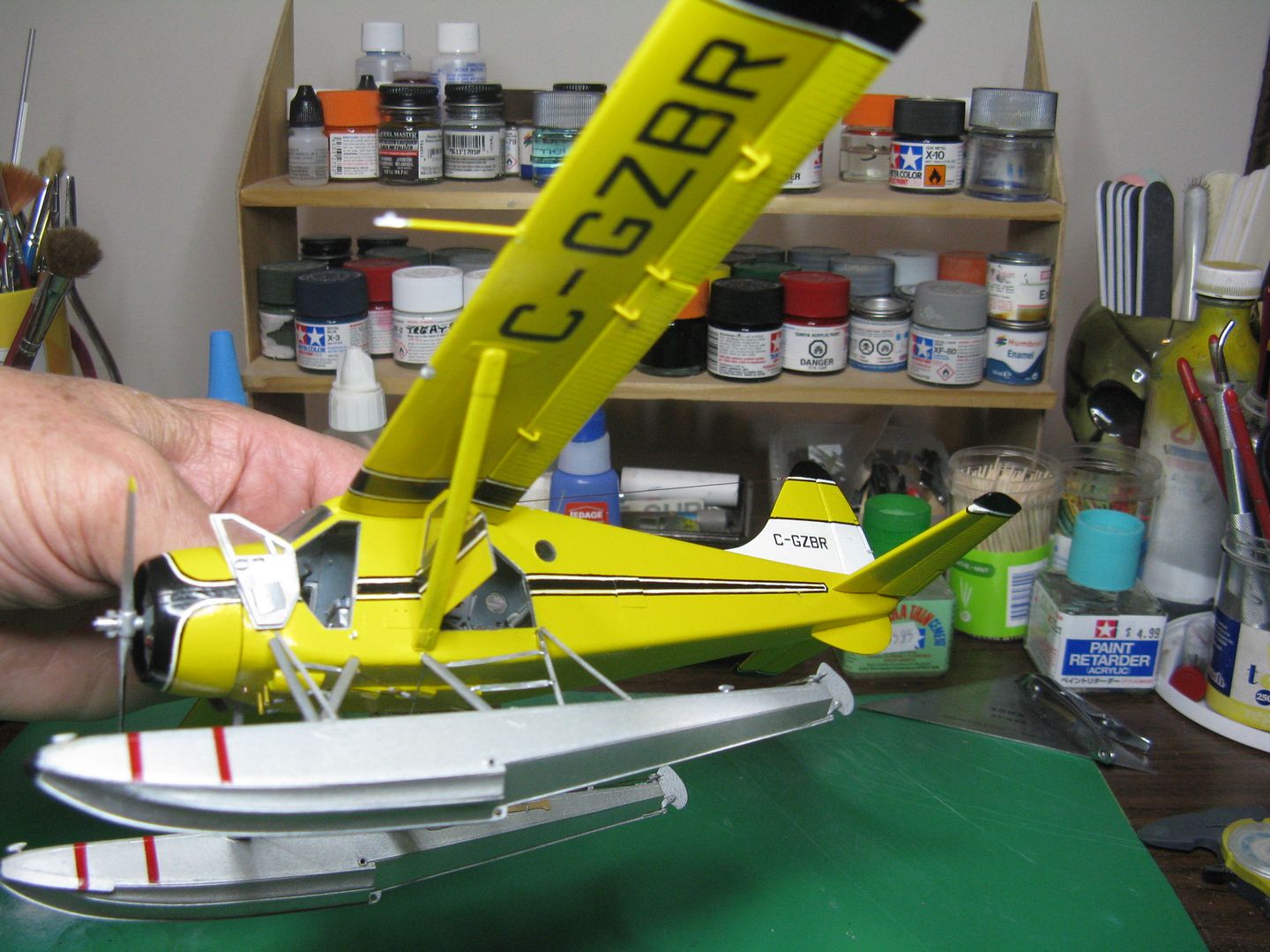
Anyway, here's the finished product. The antennas are from bits of wire, as is the pitot tube. Finally, J-Bot did his usual magic with the decals, thanks Jim.
On to the Frightener!
Well, stick a fork in this one. The rest of the assembly was pretty straightforward, consisted of adding the tail feathers and then the floats. After that was done glue on the wings and there you have it.
The floats went on well, but after I had it all squared away I didn't like the way it sat. I had used the kit float struts, but with the decks of the floats leveled, there was a very slight - but noticeable - nose down attitude. Nothing to do but very carefully remove the rear float struts and shorten them by 1/32' and Viola! problem solved. Next came connecting up the water rudder cables and installing the bracing wires. Here's the pull-up cable, that has both the cables from the water rudders attached to that nifty little dookickey I constructed some time ago, now glued to the left hand cockpit wall with the end of the cable protruding through a conduit in the cockpit floor.
The main rudder directional control cables are attached to two little torque tubes that protrude through the bottom of the fuselage, with the upper ends attached to the rudder torque tube beneath the cockpit floor.
And here's everything attached to the proper holes in the water rudder tiller.
After adding the flaps and ailerons I decided to make some new flap hangers using the patented squeeze-a-bit-of-wire-to-the-correct-shape method, thusly. Take a piece of wire and bend it to the correct shape...
...Squeeze it flat with a pair of duck-billed pliers...
...Firkytoodle the heck out of it to correct the profile, and install in the existing holes in the underside of the wing.
There is a boarding 'ladder' that comprises an integral part of the rear float strut assembly. I used a bit of wire to simulate that as well as the ladder steps. This airplane has square pieces of angle metal attached to the steps to afford a more secure step, so I made some tiny angles using beverage can, and glued them to the wire steps. Neato! The other strut that runs from the top of the ladder to the outside deck angle of the left float only, is the rear strut of the canoe strut assembly. There is a forward strut also, running from just forward of the cockpit door sill to the outside edge of the float. You could carry a fairly large boat/canoe on the Beaver. The largest I've flown was 16' aluminum canoes. If you were carrying square stern boat, the square end always went forward. This avoided the large area of low pressure that would occur behind the square stern when airborne, thus affecting elevator effectiveness if the boat were carried in the conventional way. Strangest external load I ever carried was a dozen bed springs, six a side, attached to the float struts. They made an unholy whistling noise in cruise, fortunately it was a short trip.
Anyway, here's the finished product. The antennas are from bits of wire, as is the pitot tube. Finally, J-Bot did his usual magic with the decals, thanks Jim.
On to the Frightener!
phantom II
Master at Arms
Beautiful build
Cheers, Christian B)
Cheers, Christian B)