chrispisme
Well-known member
beautiful work dude!

Modelers Alliance has updated the forum software on our website. We have migrated all post, content and user accounts but we could not migrate the passwords.
This requires that you manually reset your password.
Please click here, http://modelersalliance.org/forums/login to go to logon page and use the "Forgot your Password" option.


Thank you James.
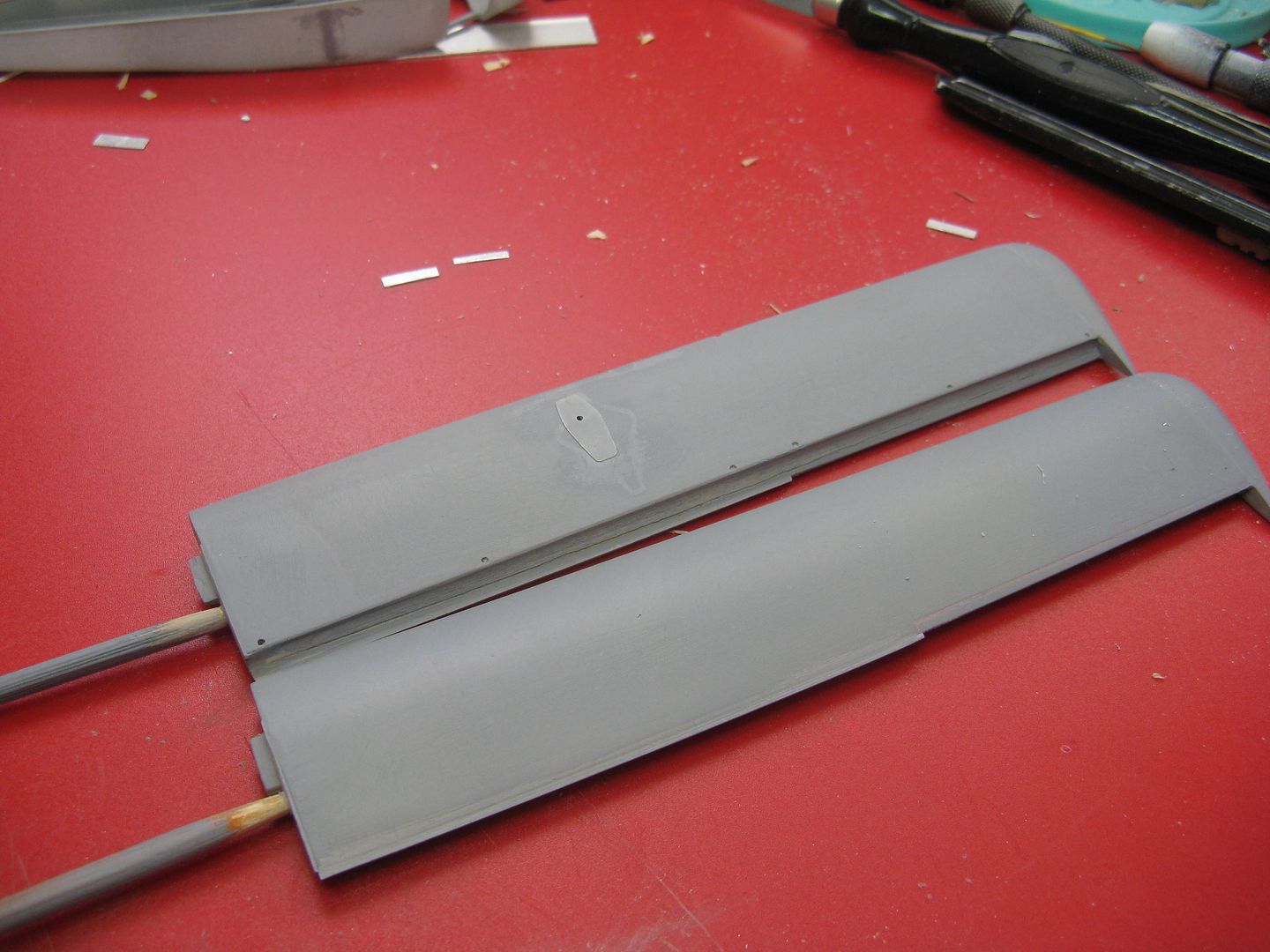
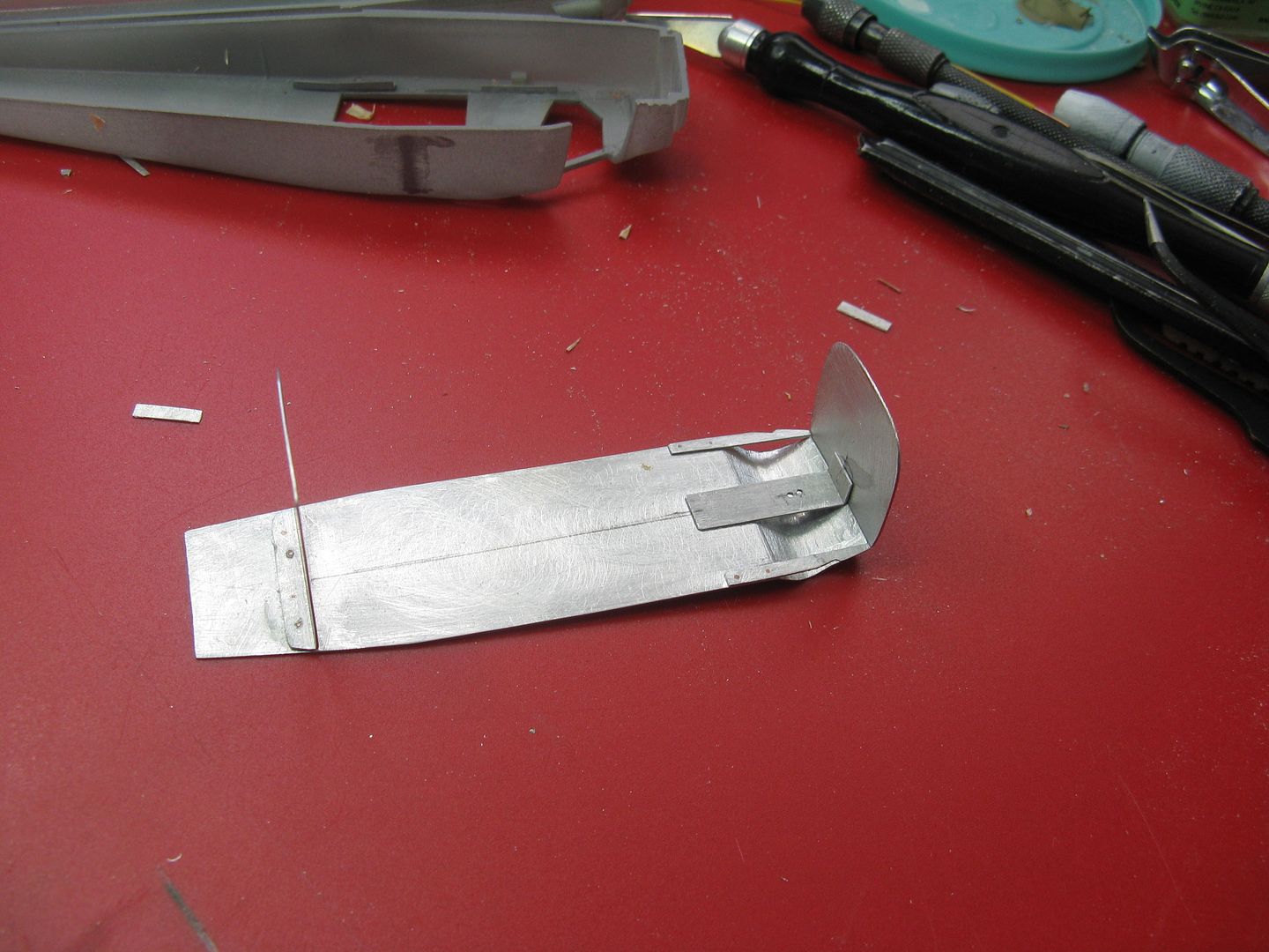
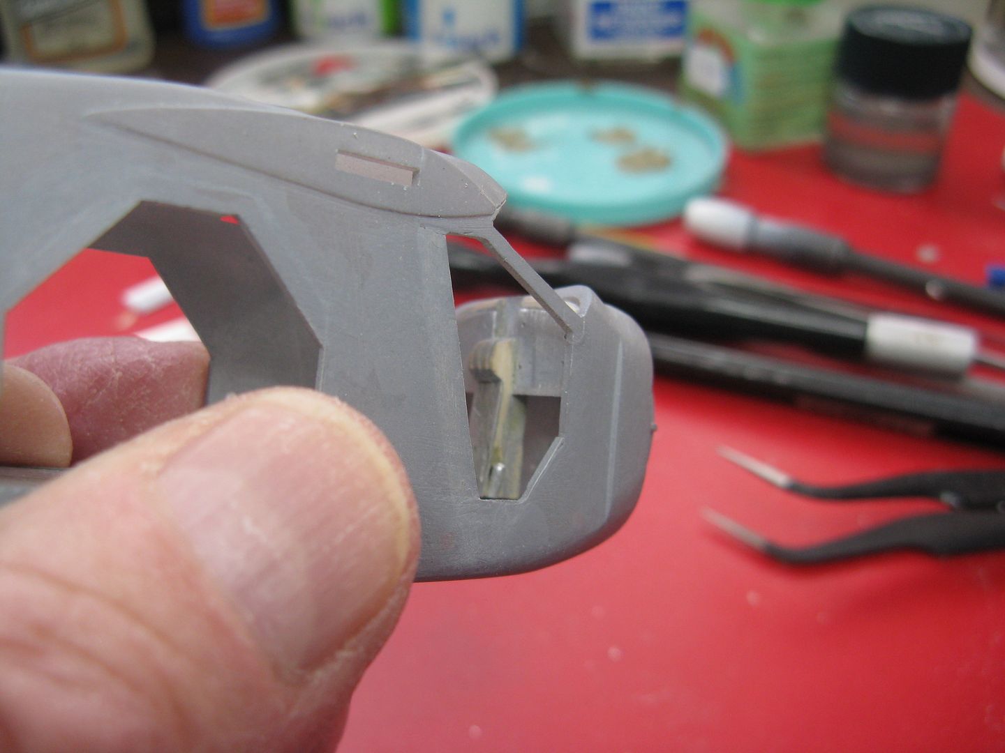
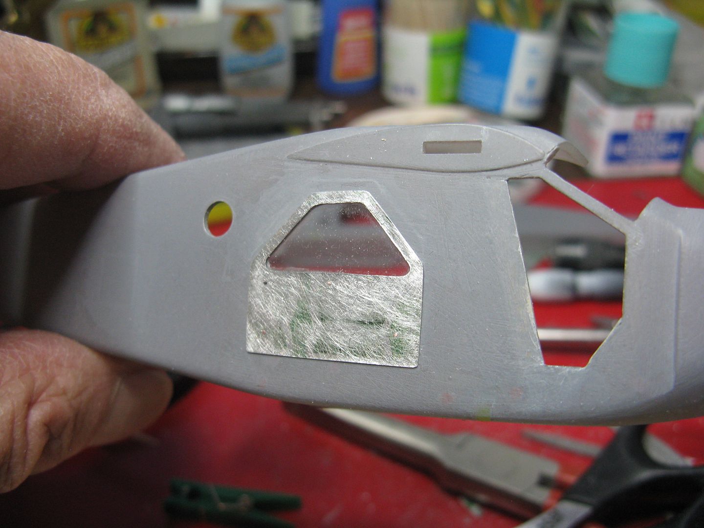
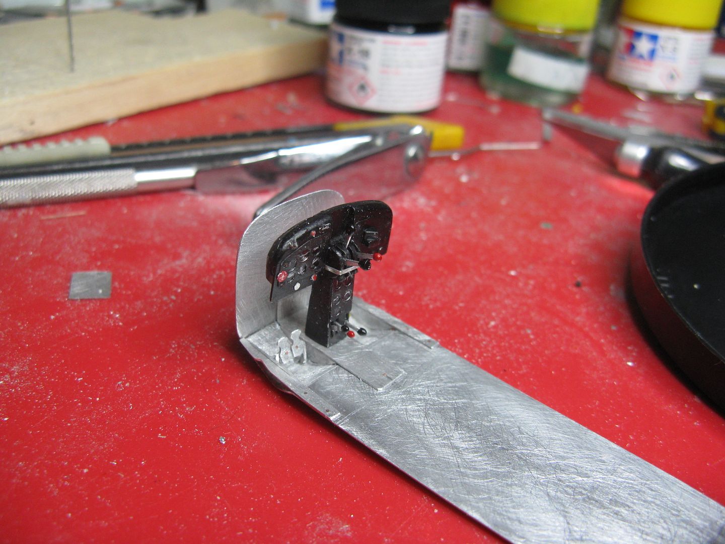
How to make a door sandwich.
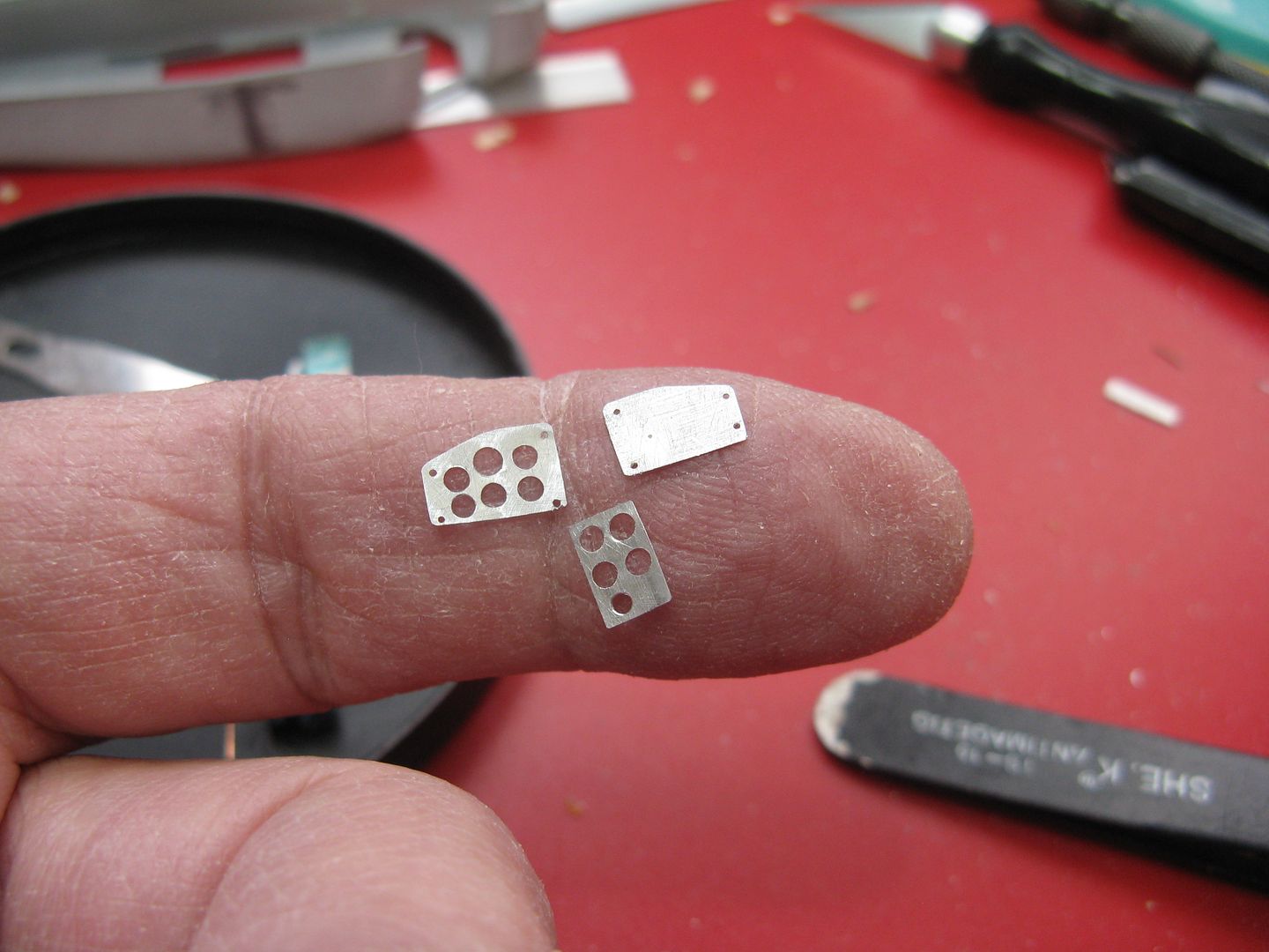
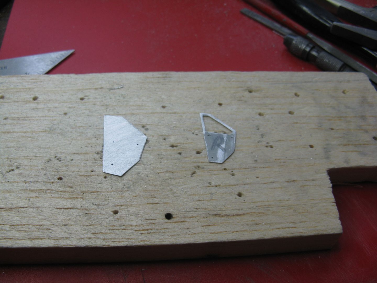
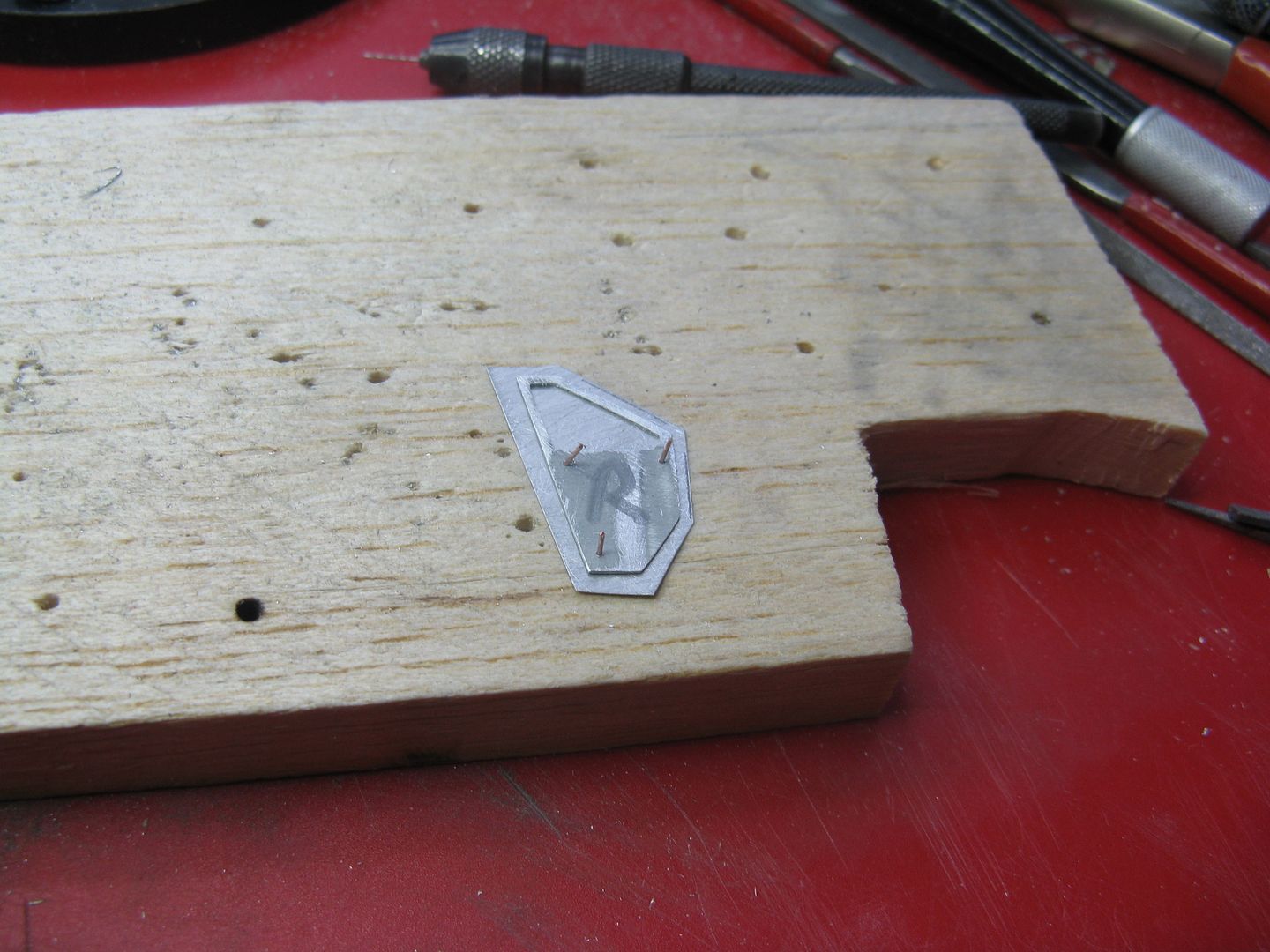
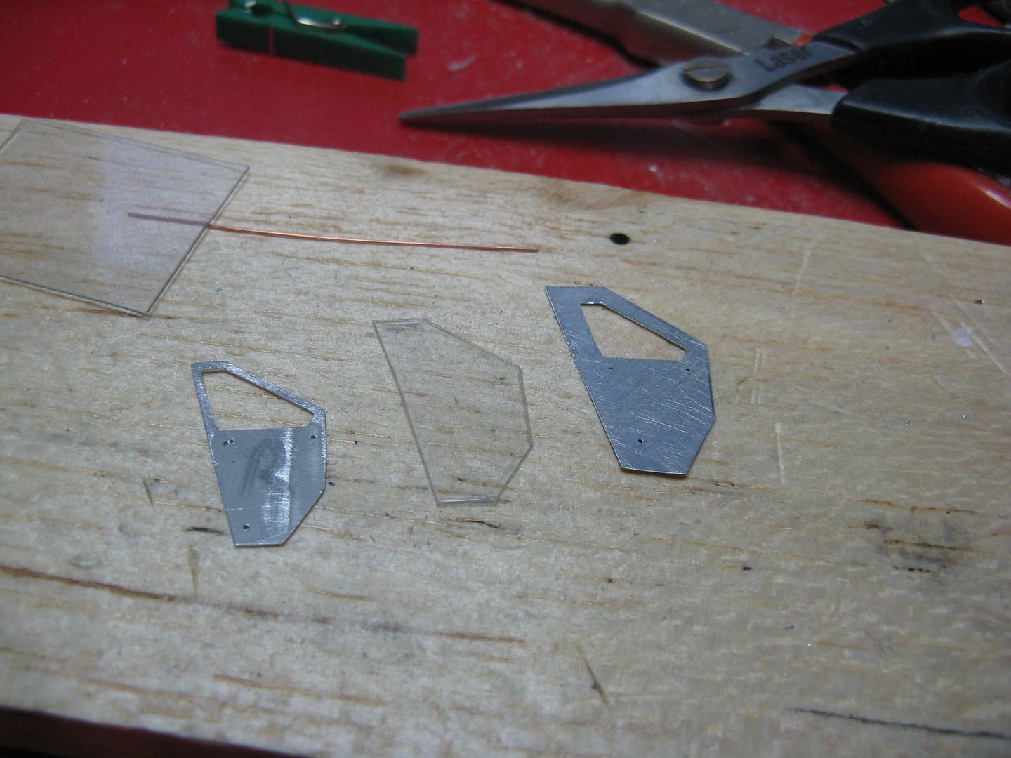
First, cut a piece of .015 scrap aluminum to fit the door opening, in this case the rh cockpit door, and drill and file out the window opening. This will be the door inner panel. Cut an outer panel slightly larger than the inner panel...
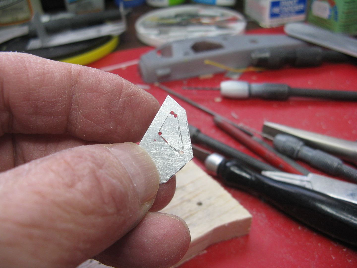
...And drill three locating holes - one of which will become the door handle hole - so's you can mark out the window opening on the outer panel.
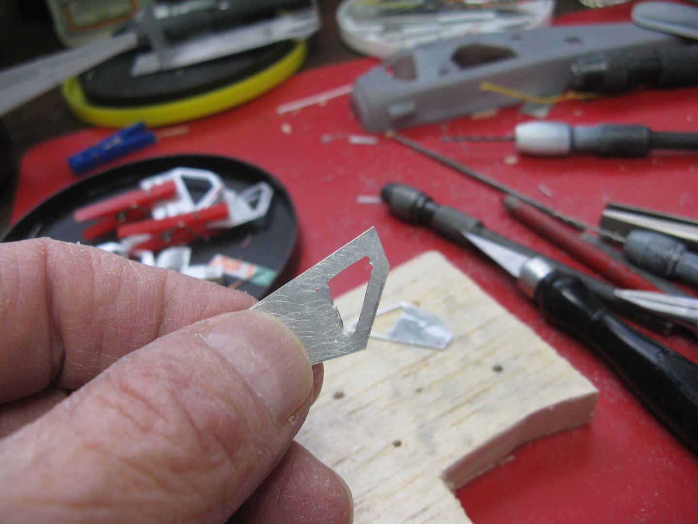
Mark the window opening and rough it out...
...Then finish it with various shapes of needle files.
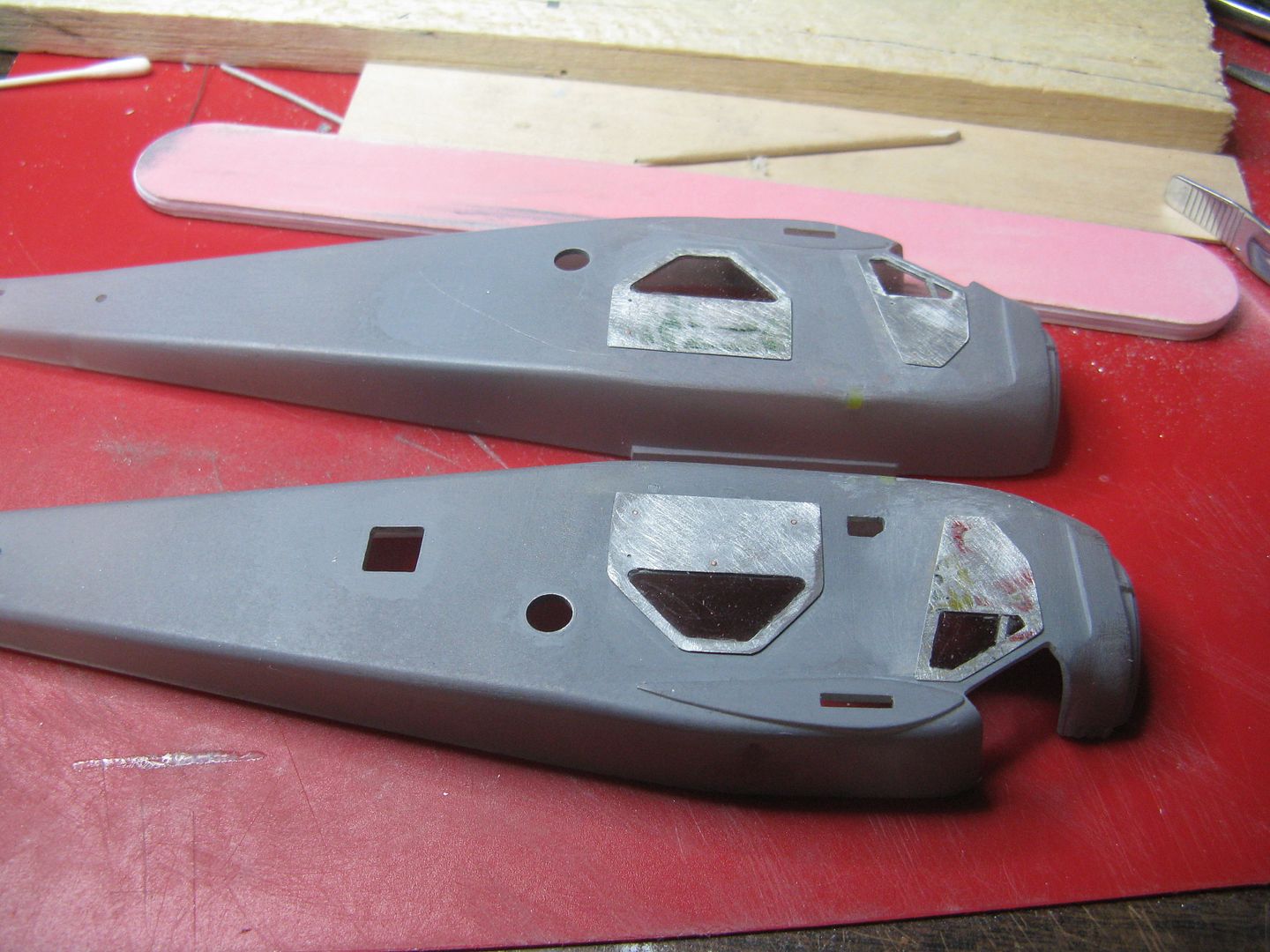
Repeat three times.
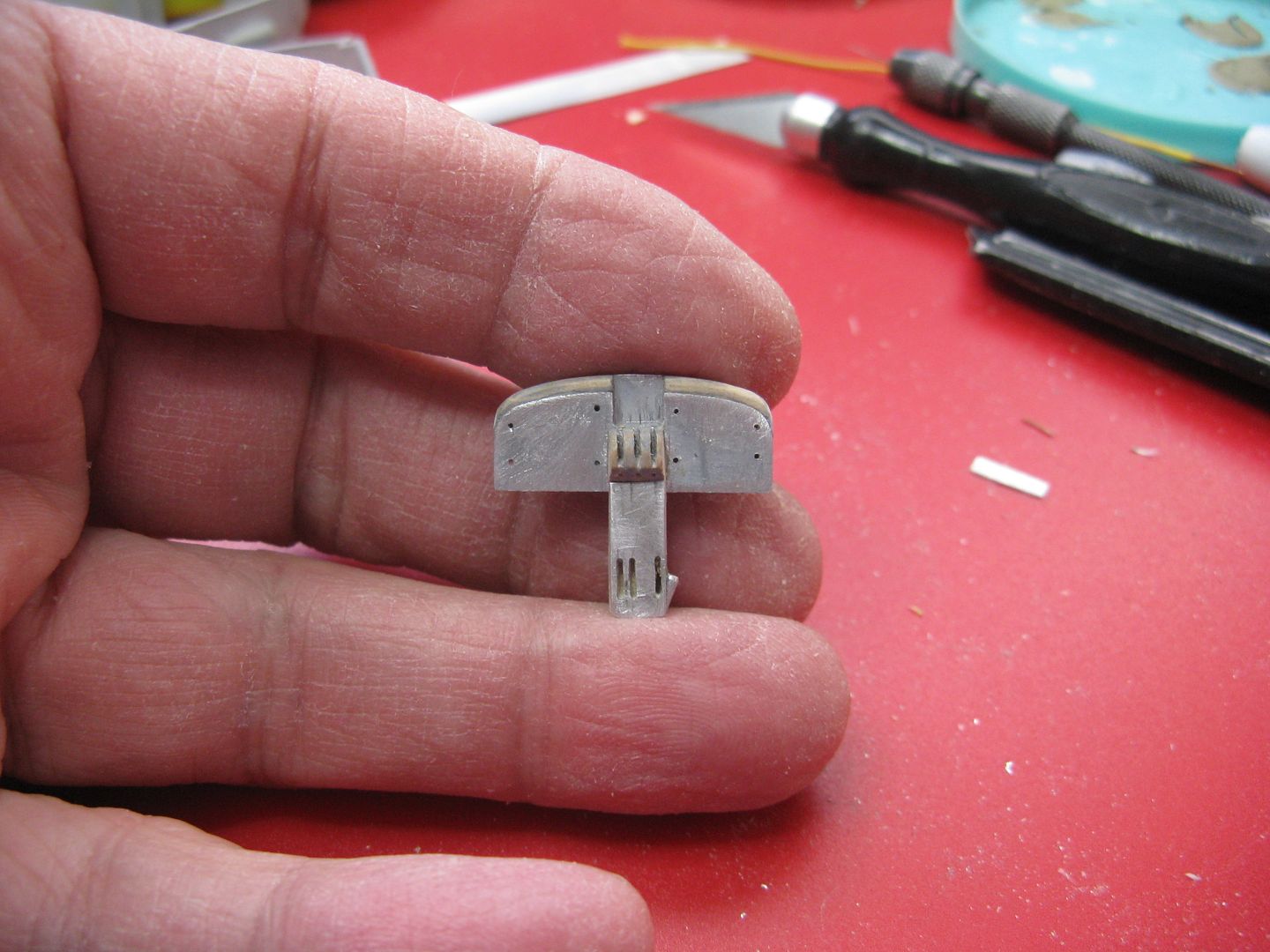
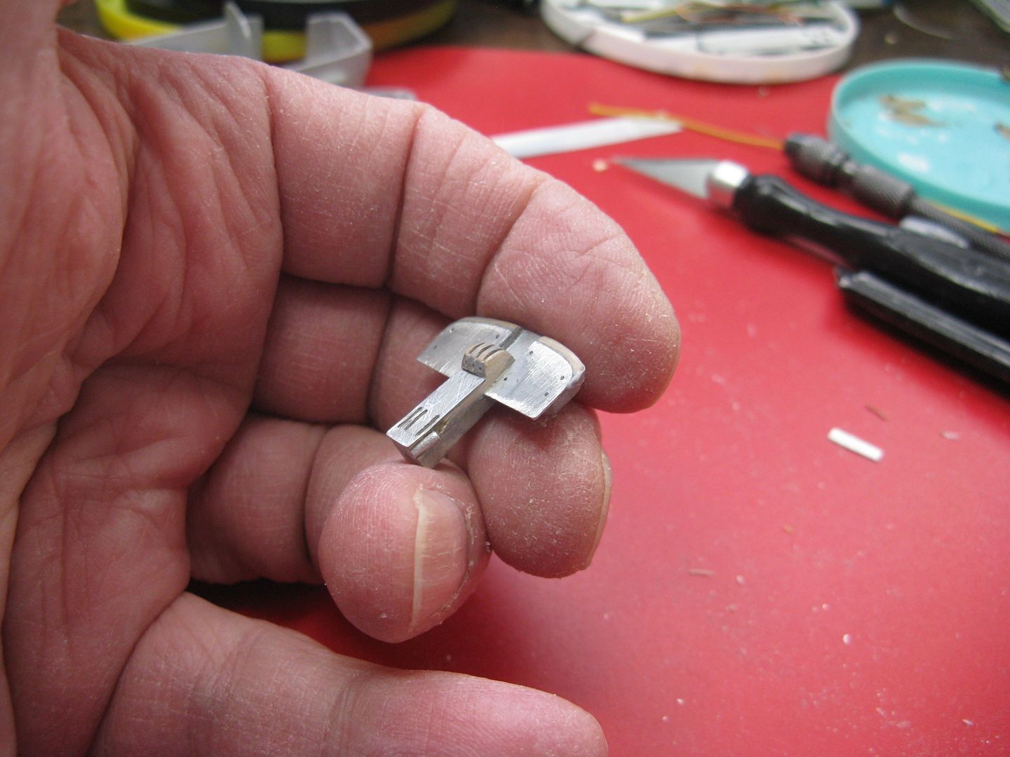
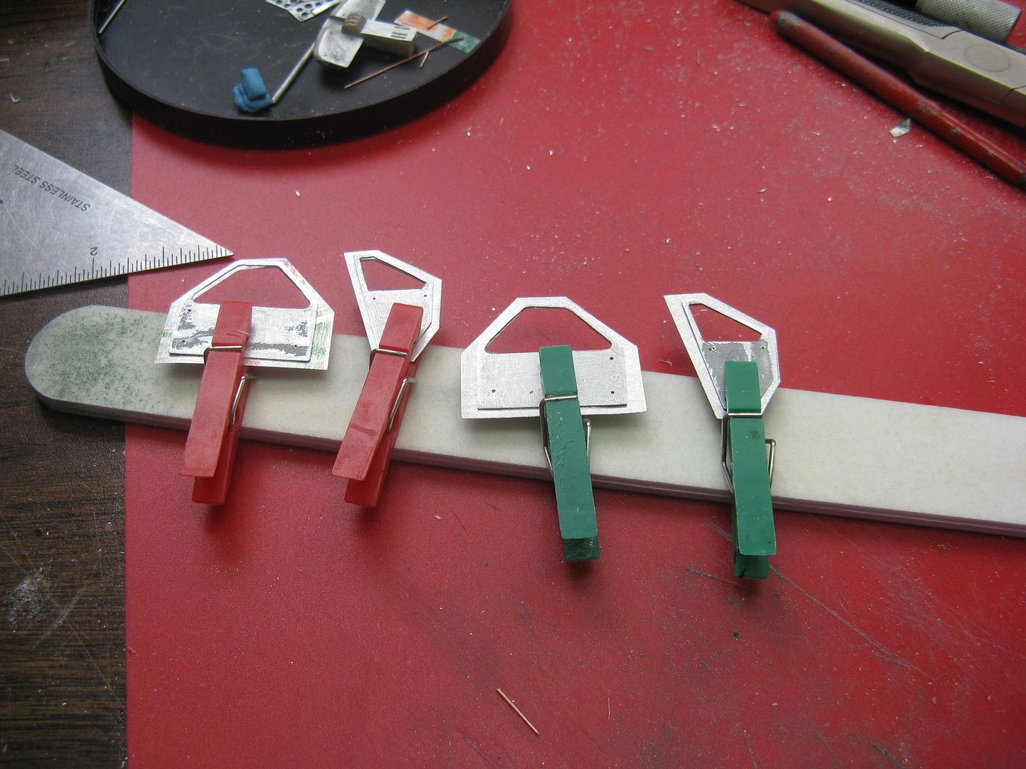
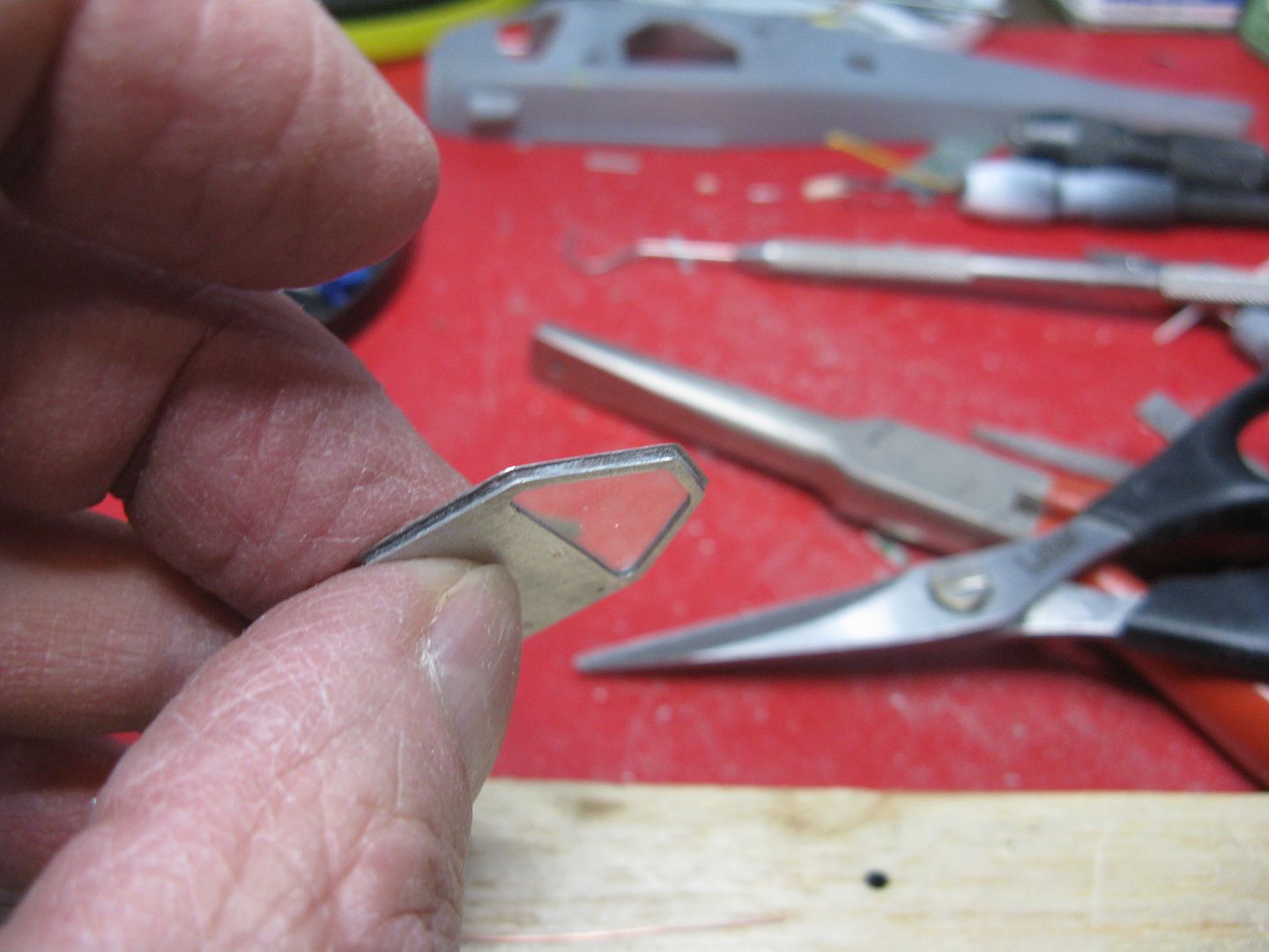
Take a piece of .020 acrylic and cut to the exact size of the inner door panel, then glue it to the outer side of the inner panel. Got that, outer side of inner panel, not like I have done sometimes. :facepalm
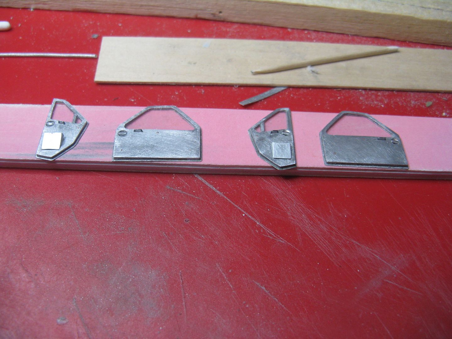
Once the glue has dried - I use that new Gorilla Glue clear by the way, nearly as good as epoxy without the mixing hassle - using the inner panel as a template, drill out the three locating holes in the clear panel so's the window opening you so painstakingly made in the outer lines up properly with the inner window opening. Glue the outer panel to the clear part and after the glue has dried trim the outer panel so there is a 1/64" overlap. This will keep the door from falling into the cabin when it's in place.
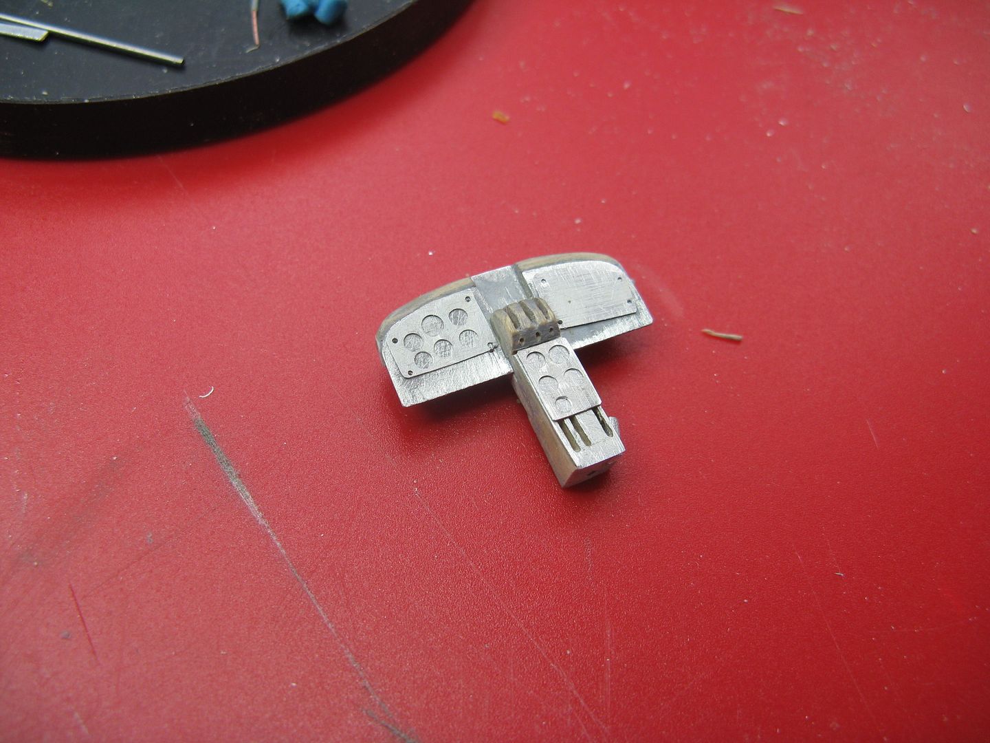
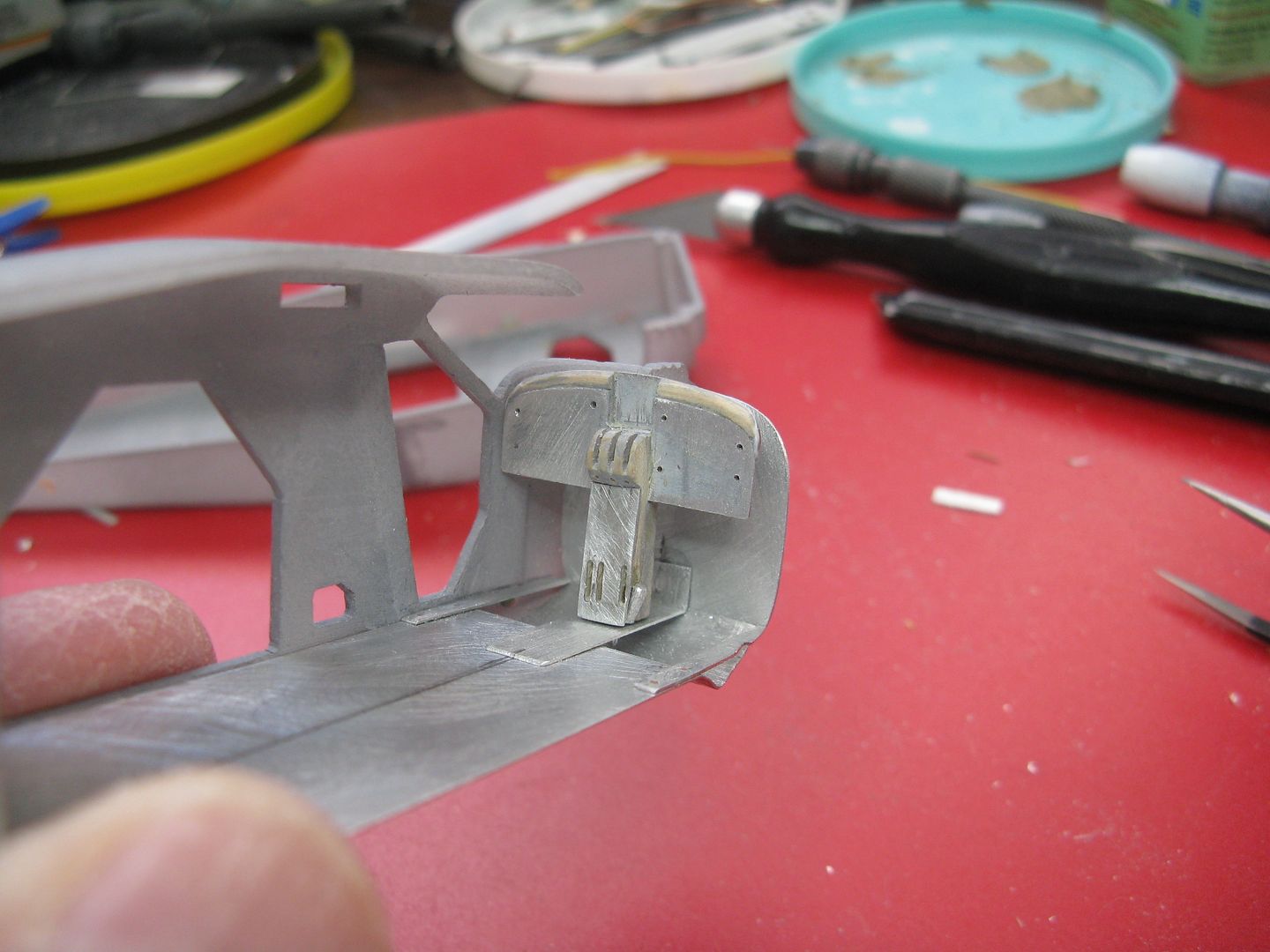
Repeat as necessary. I also use a 26ga wire pin in the locating holes to help hold things together, and bits of wire and aluminum as door handles and grab handles.
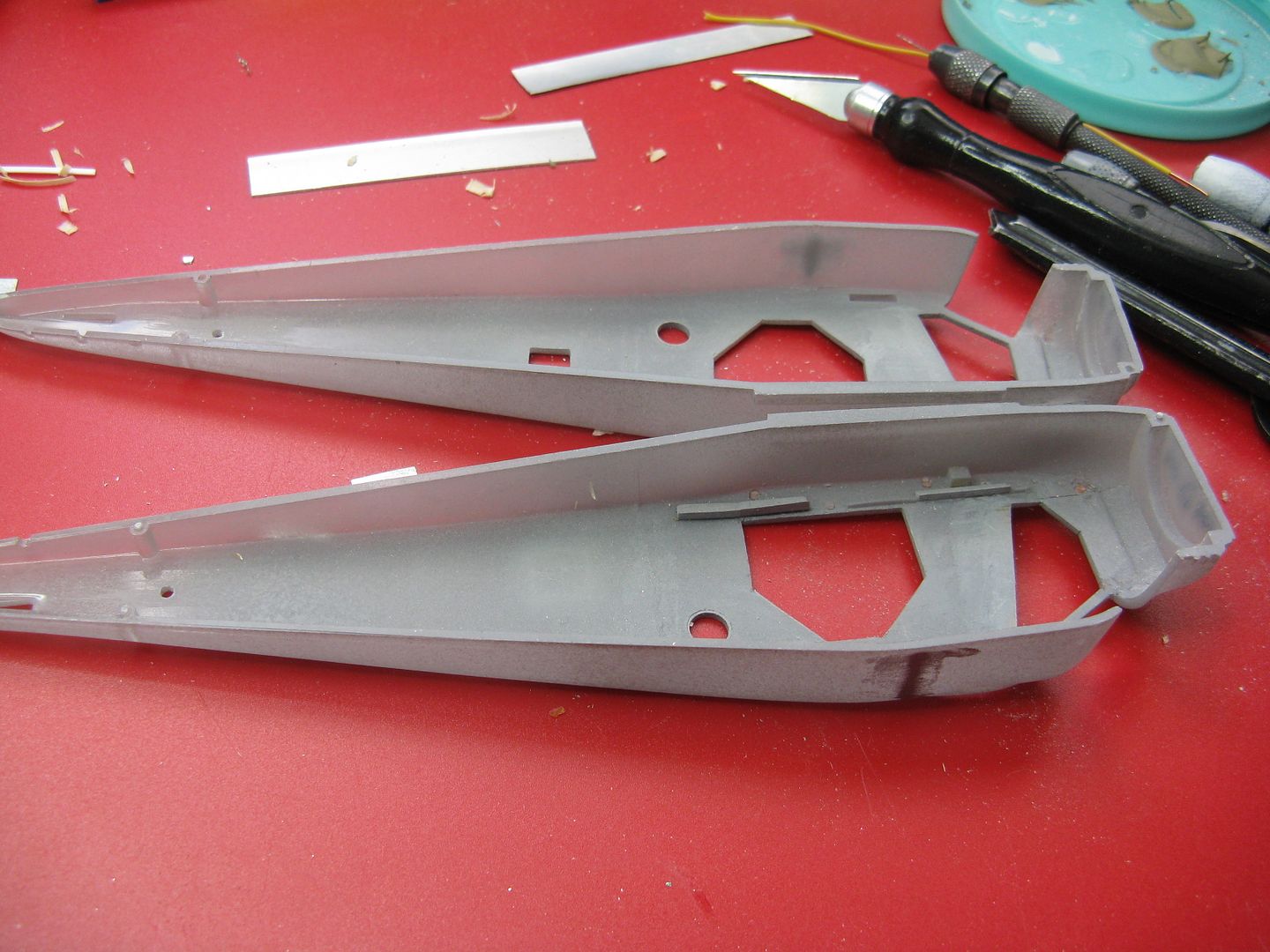
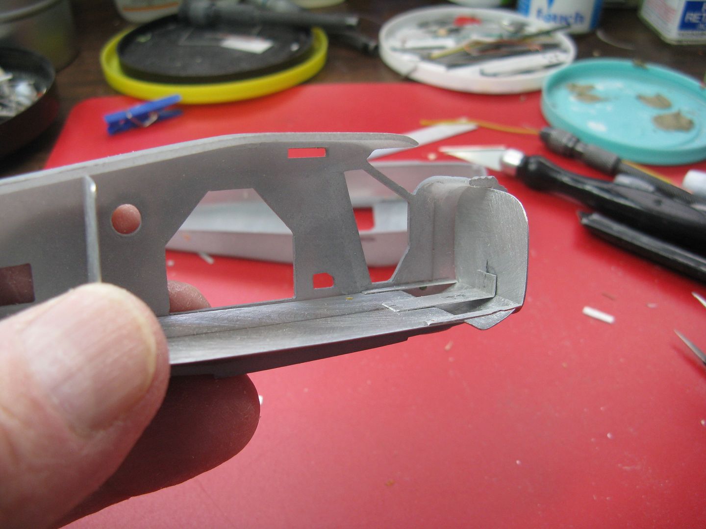
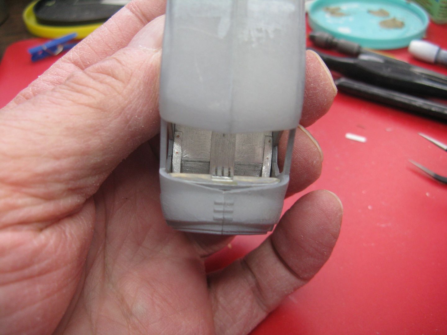
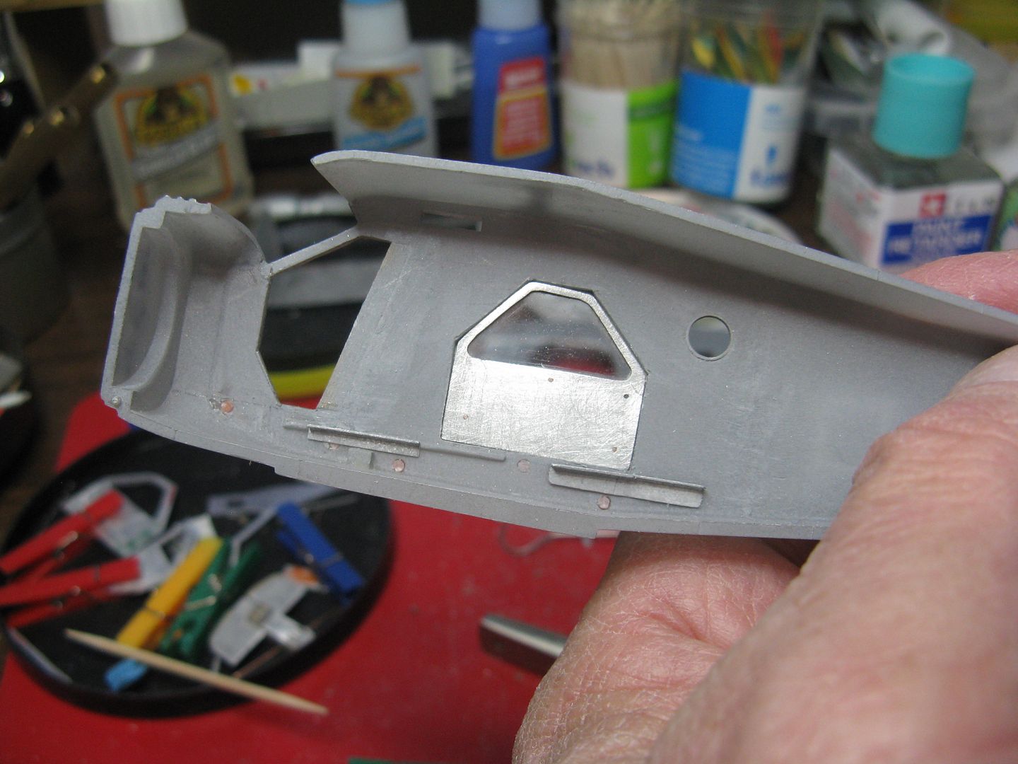
Viola! we have doors.
C'mon baby light my fire..
 :drinks