Pit Road 1/144 Me 323D-4
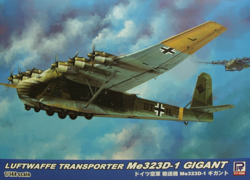
The Me 323 was the result of a 1940 German requirement for a large assault glider in preparation for Operation Sea Lion, the projected invasion of Great Britain. The DFS 230 light glider had already proven its worth in the Battle of Fort Eben-Emael in Belgium (the first ever assault by gliderborne troops), and would later be used successfully in the invasion of Crete in 1941.
However, in order to mount an invasion across the English Channel, the Germans would need to be able to airlift vehicles and other heavy equipment as part of an initial assault wave. Although Operation Sea Lion was cancelled, the requirement for a heavy air transport capability still existed, with the focus now on the forthcoming Operation Barbarossa, the invasion of the Soviet Union.
On 18 October 1940, Junkers and Messerschmitt were given just 14 days to submit a proposal for a large transport glider. The emphasis was still very much on the assault role: the ambitious requirement was to be able to carry either an 88 mm gun and its half-track tractor, or a Panzer IV medium tank. The Junkers Ju 322 Mammut reached prototype form but was eventually scrapped due to difficulties in procuring the necessary high-grade timber for its all-wood construction and, as was discovered during the Mammut's only test flight, an unacceptably high degree of instability inherent in the design. The proposed Messerschmitt aircraft was originally designated Me 261w — partly borrowing the designation of the long-range Messerschmitt Me 261, then changed to Me 263 (later re-used for Messerschmitt's improved rocket fighter design) and eventually became the Me 321. Although the Me 321 saw considerable service in Russia as a transport, it was never used for its intended role as an assault glider.
Early in 1941, as a result of feedback from Transport Command pilots in Russia, the decision was taken to produce a motorized variant of the Me 321, to be designated Me 323. It was decided to use French Gnome et Rhône GR14N radial engines rated at 1,164 hp for take-off as used in the Bloch MB.175 aircraft; using French engines was thought to place no burden on Germany's over strained industry.
Initial tests were conducted using four Gnome engines attached to a strengthened Me 321 wing, which gave a modest speed of 130 mph – 50 mph slower than the Ju 52 transport aircraft. A fixed undercarriage was fitted, which comprised four small wheels in a bogie at the front of the aircraft with six larger wheels in two lines of three at each side of the fuselage, partly covered by an aerodynamic fairing. The rear wheels were fitted with pneumatic brakes, and could stop the aircraft within 660 ft.
The four-engine Me 323C was considered merely a stepping stone to the six-engine D series; it still required the five-engine Heinkel He 111Z Zwilling or the highly dangerous, "vic-style" Troika-Schlepp formation of three Messerschmitt Bf 110 heavy fighters and under wing mounted Walter HWK 109-500 Starthilfe rocket assisted takeoff units to get airborne when fully loaded, but it could return to base under its own power when empty. This was clearly not much better than the Me 321, so the V2 prototype became the first to have six engines and flew for the first time in early 1942, becoming the prototype for the D series aircraft.
The selection of the six engines, and their specific placement on the wing's leading edge, were fitted to reduce torque – a trio of counterclockwise rotation engines mounted on the port wing, and a trio of clockwise rotation engines on the starboard wing as seen forward from behind each engine, resulting in the props rotating "away" from each other at the tops of their arcs.
Maximum payload was around 12 tonnes, although at that weight the Hellmuth Walter Werke-designed Walter HWK 109-500 Starthilfe RATO (rocket assisted takeoff) units used on the Me 321 were required for take off. The RATOs were mounted beneath the wings outboard of the engines, with the wings having underside fittings to take up to a total of four RATO units. The cargo hold was 36 ft long, 10 ft wide and 11 ft high. The typical loads it carried were: One 15 cm FH18 field artillery piece (5.5 ton) accompanied by its Sd.Kfz.7 halftrack transport vehicle (11 ton); two 4 ton trucks; 8,700 loaves of bread; an 88 mm Flak gun and accessories; 52 drums of fuel; 130 men or 60 stretchers.
Some Me 321s were converted to Me 323s, but the majority were built as six-engine aircraft from the beginning; early models were fitted with wooden two-blade propellers, which were later replaced by metal, three-blade variable-pitch versions.
The Me 323 had a maximum speed of only 136 mph at sea level and speed dropped with altitude. For defensive armament, it was armed with five 13 mm MG 131 machine guns firing from a dorsal position behind the wings and from the fuselage. They were manned by the extra gunners, radio operator and engineers.
The Kit
Note: This kit appears to be the same as the one released under the Great Wall Hobby brand, going so far as using a modified version of the same box art, So I am assuming they are the same kits. I'm not sure which one was the chicken and which was the egg. The Pit Road kit was available from Hobby Link Japan before the Great Wall kit so that is what I'm reviewing.
The Pit Road kit comes in a sturdy top open tray type box with a thin cardboard top and a corrugated bottom half. The box is about the size that 1/48 scale fighters typically come in and is pretty well filled with sprues. The box features nice artwork on the top and the two longer sides feature photos of the competed kit on one side and profiles of marking options on the other. All in all a nice package. Inside the box one finds 11 sprues molded in a light greenish gray color. Each one is in it's own cellophane bag which is stapled closed, even the duplicate sprues. High marks for that ! There are also two sprues of clear parts also individually wrapped. There is one large sprue that pretty much fills the bottom of the box and contains the wing parts but the balance of the sprues are all fairly small.
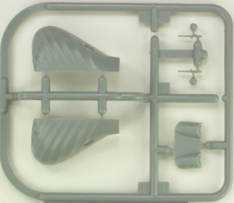
The parts are crisply molded with a smooth matte finish. The parts are virtually flash free and the sprue attachment points are either placed on mounting surfaces or where possible on edges that won't be seen when assembled. I like this feature but it's not universally liked, at least the ones on mating surfaces. The attachment points are reasonably sized and should be easy to clean up. Mold parting seams are very fine and should be easy to clean up as well. The surface features recessed panel lines which seem to be a bit smaller than I've seen on other kits in this scale. I question the panel lines supplied on the wings as the wing was plywood and fabric covered and photos I've seen show a fairly smooth surface. That said I'm probably not inclined to fill them in. The fabric surfaces are probably a bit exaggerated for the scale but photos of the prototype seem to show the fabric a bit more saggy than is the norm, possibly due to the wider spacing of the support structure underneath. In any event I think it will look just fine when painted.
The kit is reasonably well detailed for a kit in this scale. The cockpit is pretty basic but won't be that visible. The inside features structural detail molded on and there is a floor for inside. Two side doors are supplied separately and can be posed open and the main nose doors are designed to be displayed open or closed. The gunners position in the upper fuselage needs to be cut open and there are thinned areas to make this easier. There are some ejector pin marks on the interior walls but they are so light I doubt they will be that noticeable even if you leave the front doors open.
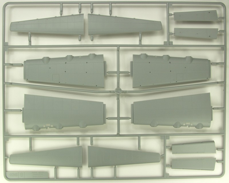
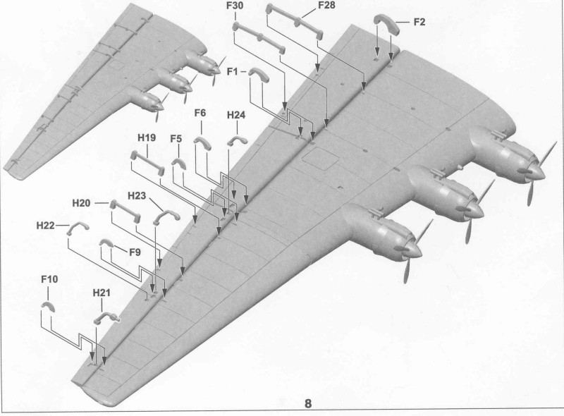
The control surfaces are supplied as separate pieces and on the wings there are a plethora of hinges and actuators to install. Many of these are probably oversized but will make things look quite busy. The wings are each in two sections with top and bottom halves, the inner section with the six engines and an outer section. I suspect it was done this way to allow the pure glider version to be done. The outer wing sections overlap a tab on the inboard section which should create a strong assembly.
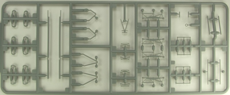
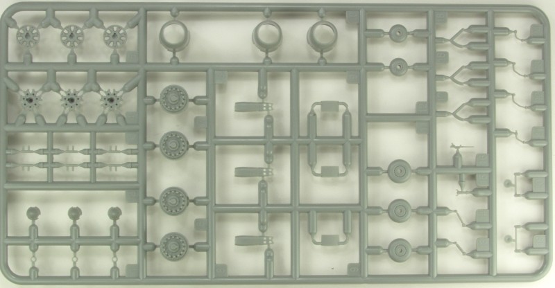
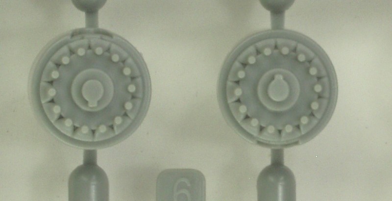
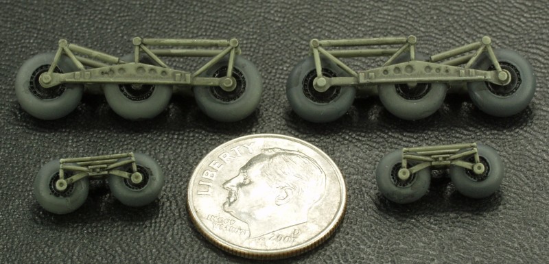
The bogie assemblies for the landing gear are well detailed but won't be all that well seen as they hide beneath a fairing. The wheels and tires are one piece moldings with an almost imperceptible hint of a mold seam. The tires are not weighted.
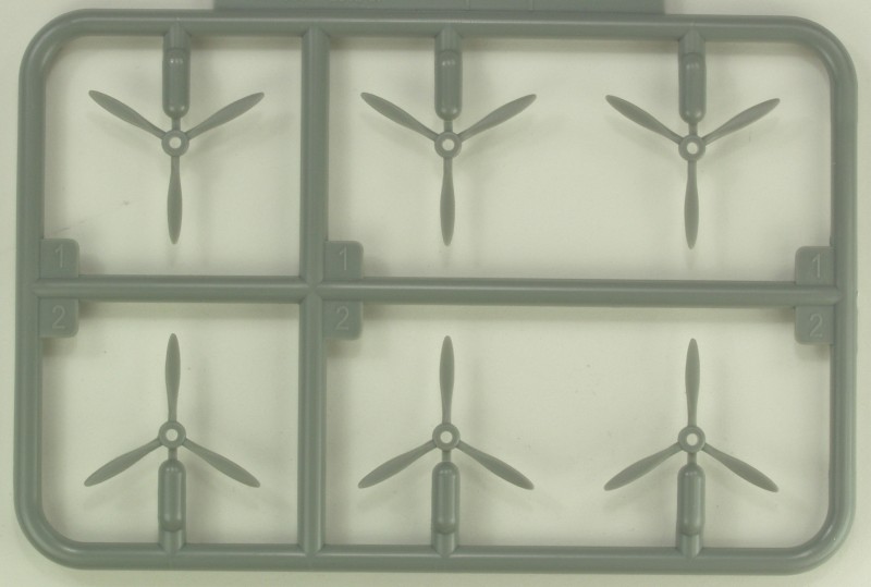
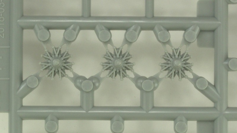
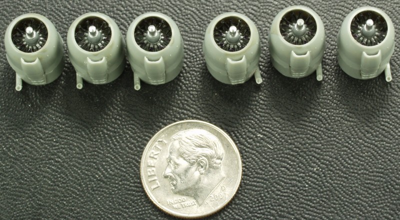
The engines are way better in detail than any I have seen in this scale, the two engine banks are molded separately. The banks are then mounted to the rear portion of the nacelle which has exhaust stubs molded into it. A separate cowling then covers them. The propellers are one piece moldings and look very nice and feature separate spinners. As on the prototype they are molded to rotate in opposite directions depending on which side of the wing they are on so one needs to check the pitch when installing.
OK, lets take a look at the plastic. First up are the fuselage halves, note the large mounting hole for the tab on the wing. No spar is supplied but there are ample gluing surfaces which should provide a strong bond.
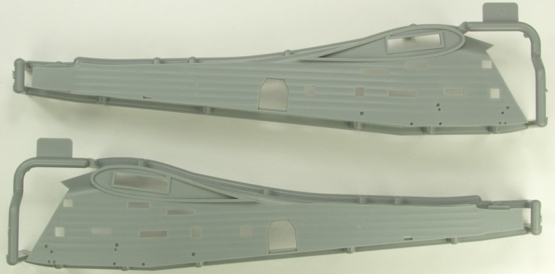
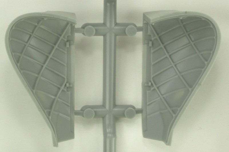
The inside detail, you can see the injector pin marks, once painted should not be that noticeable with the nose doors open and no issue at all if you close them up.
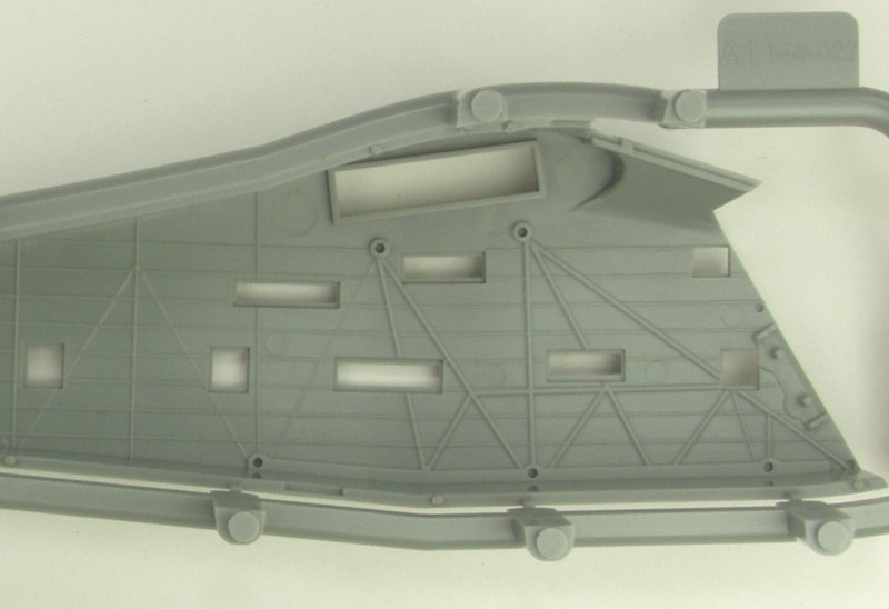
The next shot shows the rather unusual way these were molded and that the attachment points are all on the mating surfaces.
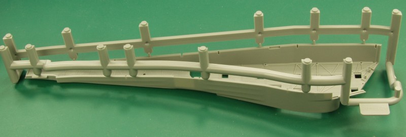
The next three are the wings, tail and control surfaces.

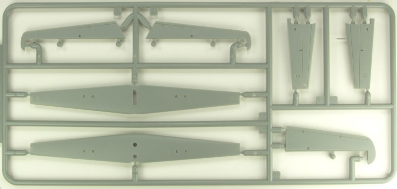
Next up are the landing gear fairings and internal detail parts.
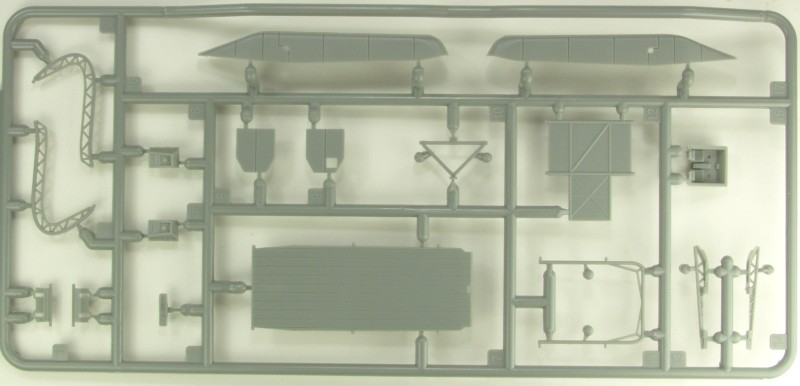
Landing gear parts, control surface actuators, wing and tail braces.
Propellers
Engines, wheels, more control surface actuators, guns, control column for the cockpit, there are two of these sprues.
The next two are close ups of the engine parts.
The next two are the nose door parts.
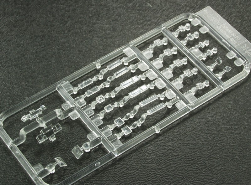
The clear parts are clear but rather thick, I don't think the thickness will be all that noticeable. The first sprue contains lots and lots of tiny windows.
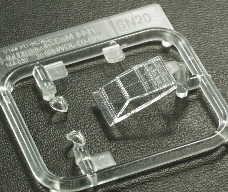
The second smaller sprue as the main cockpit glazing and the two gun blisters for the nose.
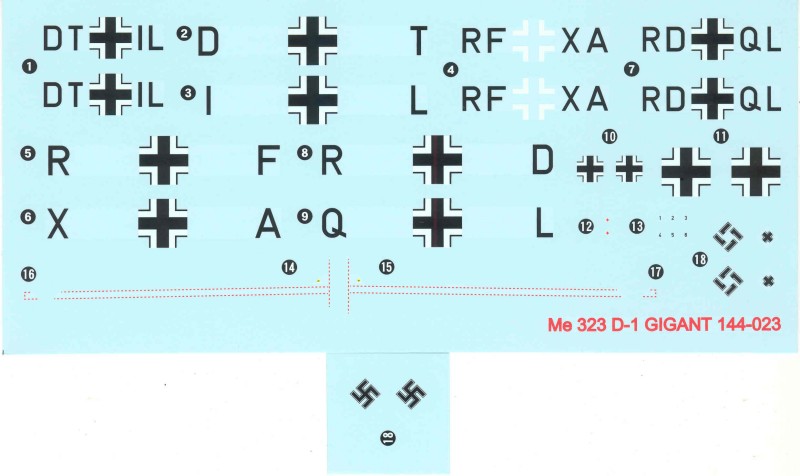
The decals are thin appearing and have a matte finish. They are all nicely printed and well registered. The letters for the bottom wing are combined with the wing wing crosses resulting in a massive amount of opportunities for silvering, my advise would be to cut them apart and apply separately. No clue on the sheet as to who printed them so I can't speak as to how well they might work. Markings for three aircraft are supplied, aircraft from Germany, Tunis and Corsica in 1943. The Swastika on the main sheet is assemble type but a second small sheet with full Swastikas is also supplied, nice !
The instructions consist of a 7" x 10 1/4" 12 page booklet stapled at the spine. All verbiage is printed in Chinese and English. The front page has a brief history with basic aircraft specifications, basic safety instructions like don't put paint or glue in your mouth, an icon chart and the start of a parts map. The second page has the balance of the parts map which includes a decal sheet showing decals not used. Page three starts the assembly which continues through page twelve in 16 steps. Assembly diagrams are of the cad style in halftone and are nicely sized and easy to follow. Options are noted where required. Color call outs are present throughout the assembly, black rectangles with a white number. These refer to the paint chart which is provided as a separate sheet. The color chart along with the painting and marking information is provided on an 11" x 16" glossy page printed in color on one side. The color chart lists the colors by a 'C' number which relates to GSI Creos Mr. Color paints. The generic color or RLM colors are listed for these as well.
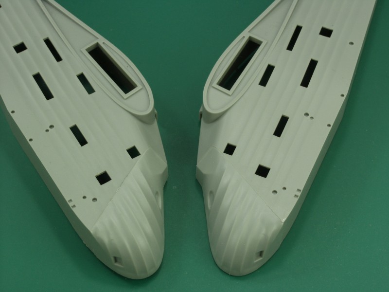
OK so how does it go together ? Well, this kit kept bugging me all the time I was reviewing it and I finally gave in to urge. I started out a little different on this kit. I decided up front that I didn't want the front doors open so that eliminated a number of parts that detail the inner portion of the doors and the door hinges. I also decided to attach the nose doors to the fuselage halves before assembling the fuselage. The fuselage nose door join was very good as shown below.
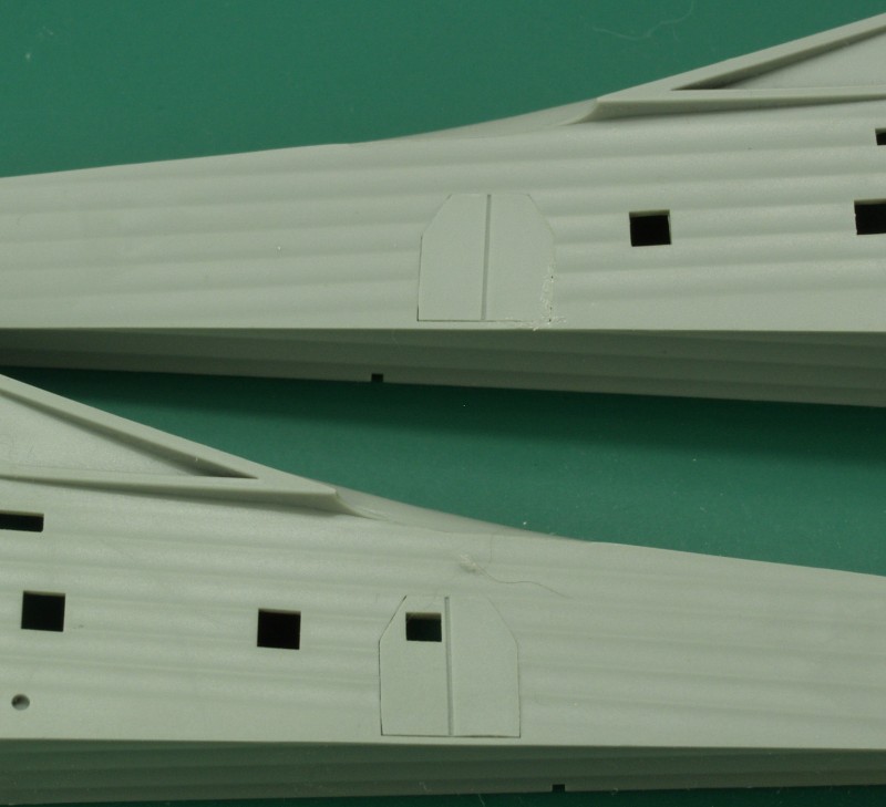
I went ahead and installed the two separate side doors which also fit quite well.
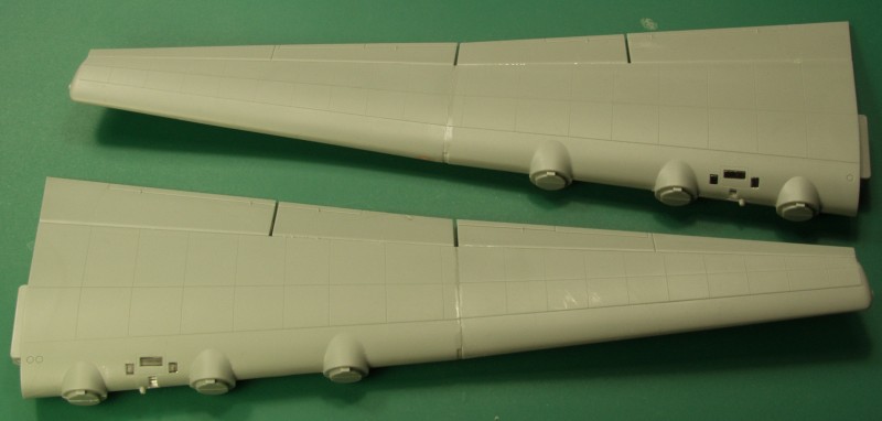
I next assembled the basic wing structures. The clear parts must be installed prior to assembling the inner wing sections. The fit of these was also quite good. Once both inner and outer sections were done they were joined and the flap and ailerons were attached. Fit again was very good.
Next I assembled the engines. These are real jewels with a very high level of detail for the scale.
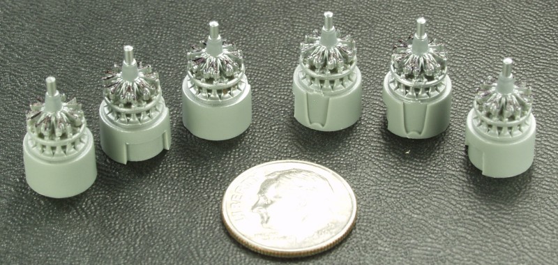
Much of that detail gets hidden with the cowlings on but it still looks better than the rather one dimensional look of engines typical in this scale.
The bogies for the landing gear are also very well detailed even though they will be mostly hidden under shrouds.
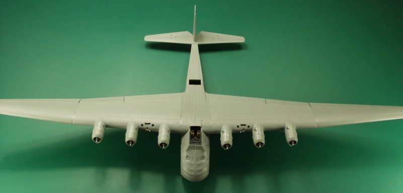
The clear parts were installed in the fuselage prior to closing it. They all fit very snugly but better than some kits where the clear parts fit very loosely or not at all. I only hope Eduard does a mask set for this as there are a lot of little windows to mask. I did lose one of the smaller ones to the carpet monster but some crystal clear should take care of it. The hole in the top for the gunners position also needed cut out. There was a recessed line on the inside to guide in cutting. I left out the main floor but did install the upper level floor behind the cockpit in case it could be seen. The cockpit can be installed after the fact and the floor alignment pegs can be reached through that opening to align them when gluing the fuselage together. Once the fuselage had cured I installed the wings and tail group. The wings have a nice solid mounting tab and all the parts fit together very well.
The cockpit, though simple isn't bad for the scale with separate control columns and instrument panel, I added some shoulder harnesses from tape. The cockpit drops in and rests on a rail on each side.
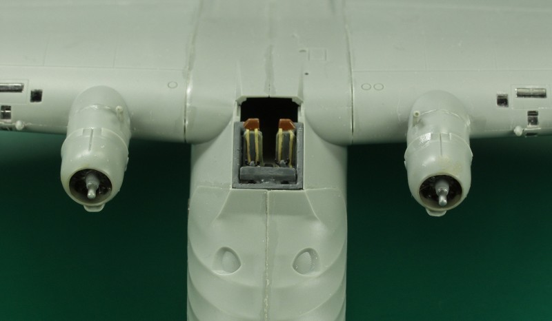
No attempt at seam work has been at this point which illustrates how well everything fit.
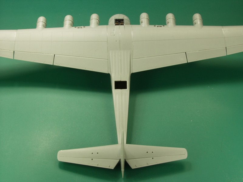
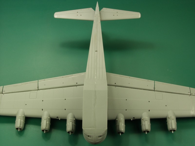
I'm going to leave off all of the wing and tail bracing until after painting as well as all of the under wing detail which consists of a plethora of control surface hinges, actuators and mass balances.
Although there is no mention of a nose weight being required in the instructions it will be a tail sitter. Photos can be found that show the prototype sitting that way when not loaded and there is a brace on the rear fuselage that can be lowered when the aircraft was being loaded to keep the nose down. This is supplied in the kit and can be mounted either up or down.
That's all the farther I'm going for this review. When I get it finished up I'll post it up in the forum.
My 2¢ worth
I'm quite impressed with this kit, molding and fit is very good, much better than any other kits I have built in this scale. It's not exactly small even in this scale and certainly nice for those who don't have room for one in a larger scale. I would be really happy to see kits as nice as this one of large aircraft like the B-36, B-47, B-49, B-52, etc.
As always, thanks for looking !
------------------------------------
