
-
Modelers Alliance has updated the forum software on our website. We have migrated all post, content and user accounts but we could not migrate the passwords.
This requires that you manually reset your password.
Please click here, http://modelersalliance.org/forums/login to go to logon page and use the "Forgot your Password" option.
You are using an out of date browser. It may not display this or other websites correctly.
You should upgrade or use an alternative browser.
You should upgrade or use an alternative browser.
Swine!
- Thread starter Stoneboat
- Start date
Duke Maddog
Well-known member
I am gobsmacked! Stunning work! I feel so inadequate!
Sherman 18
Master at Arms
Cool
:woohoo:
:woohoo:
Excellent corrections. Just out of curiosity, why didn't you just put in a strip of clear plastic (like that from a CD cover) into the slots you cut for the fuselage windows and then simply mask the clear areas? I know you can make them fit like the masterful work with the reshaped door but it seems like extra work you could have avoided (unlike the cabin door).
Regards,
Regards,

Thanks for the kind comments fellas, appreciate that.
Fair question, deserves a straight answer.
Mainly because I didn't think of it at the time, 'Course I could still do it, but I probably not. One, I like to use the kit windows, which will fit with minor modifications. The problem I have with using the strip of cd case would be the sanding and polishing and polishing and sanding required to achieve a job like Uros did on one of his models awhile back. I think it's probably six of one and half a dozen of the other, with the extra work required to remake the window openings being equal to the work required to sand and polish the one piece units. Also, when I install the headliner and cabin side panels I simply glue them to the inside of the cabin then cut the window openings out after the glue has dried.
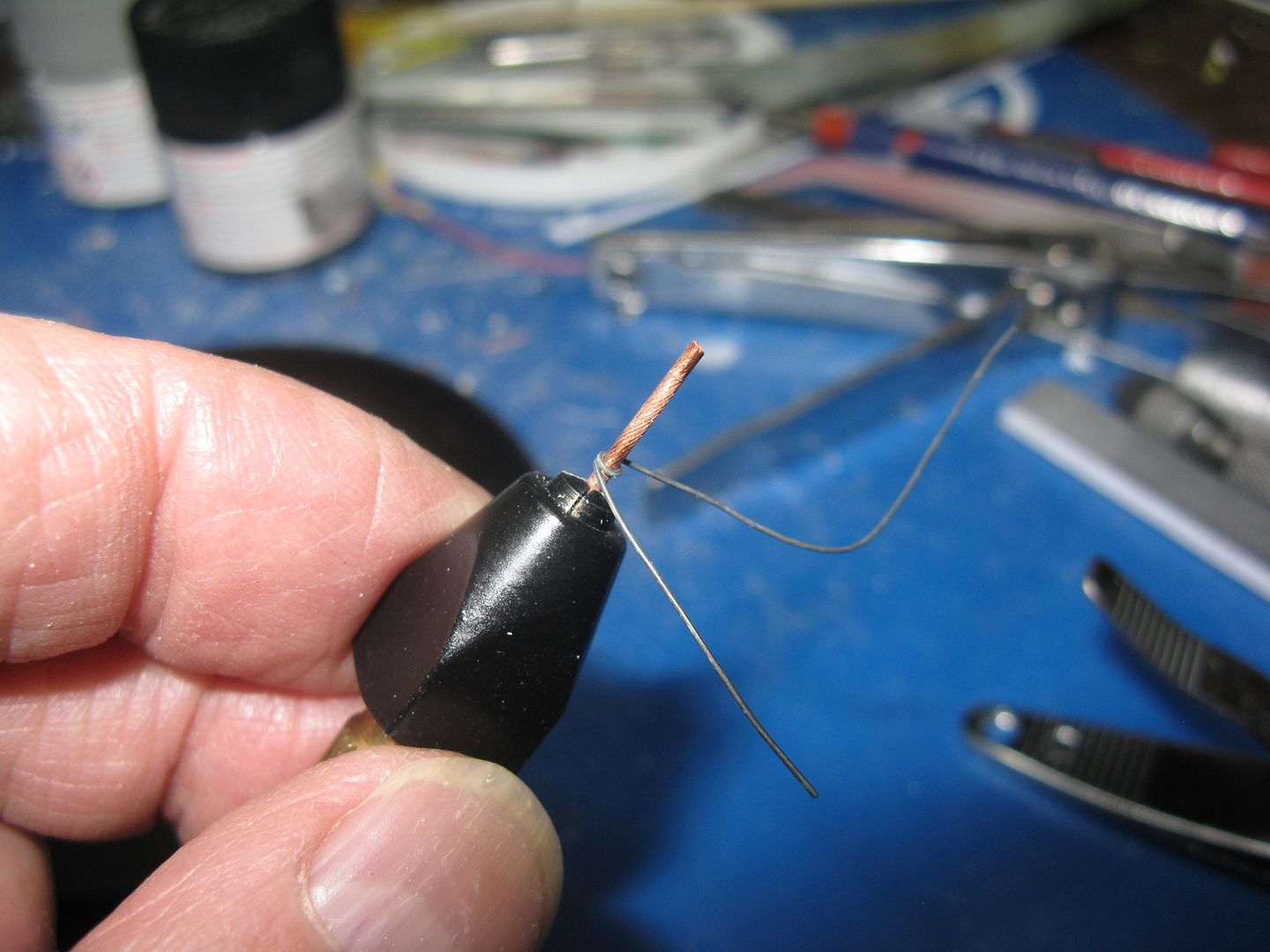
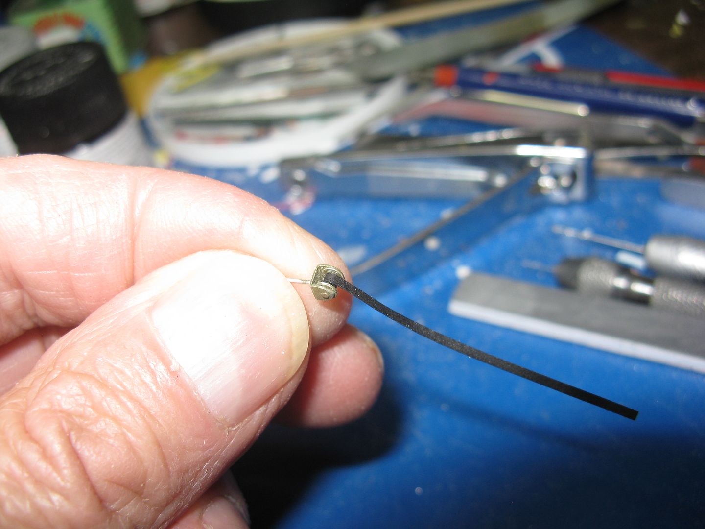
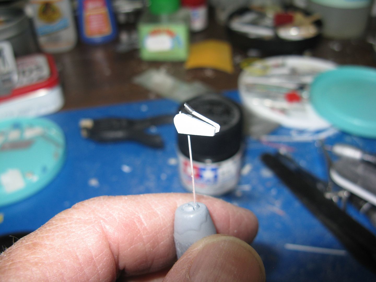
For the seatbelts, I cut some Frog tape into strips of appropriate width, then painted them satin black. To attach them to the seats, I made some eyes by wrapping a short length of 28ga wire around a convenient pin...
...Cut off the excess wire...
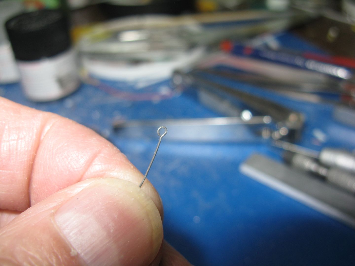
...And bend the eye 90 degrees and slip the belt into the eye, making a loop.
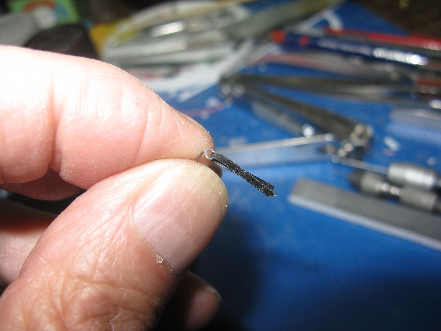
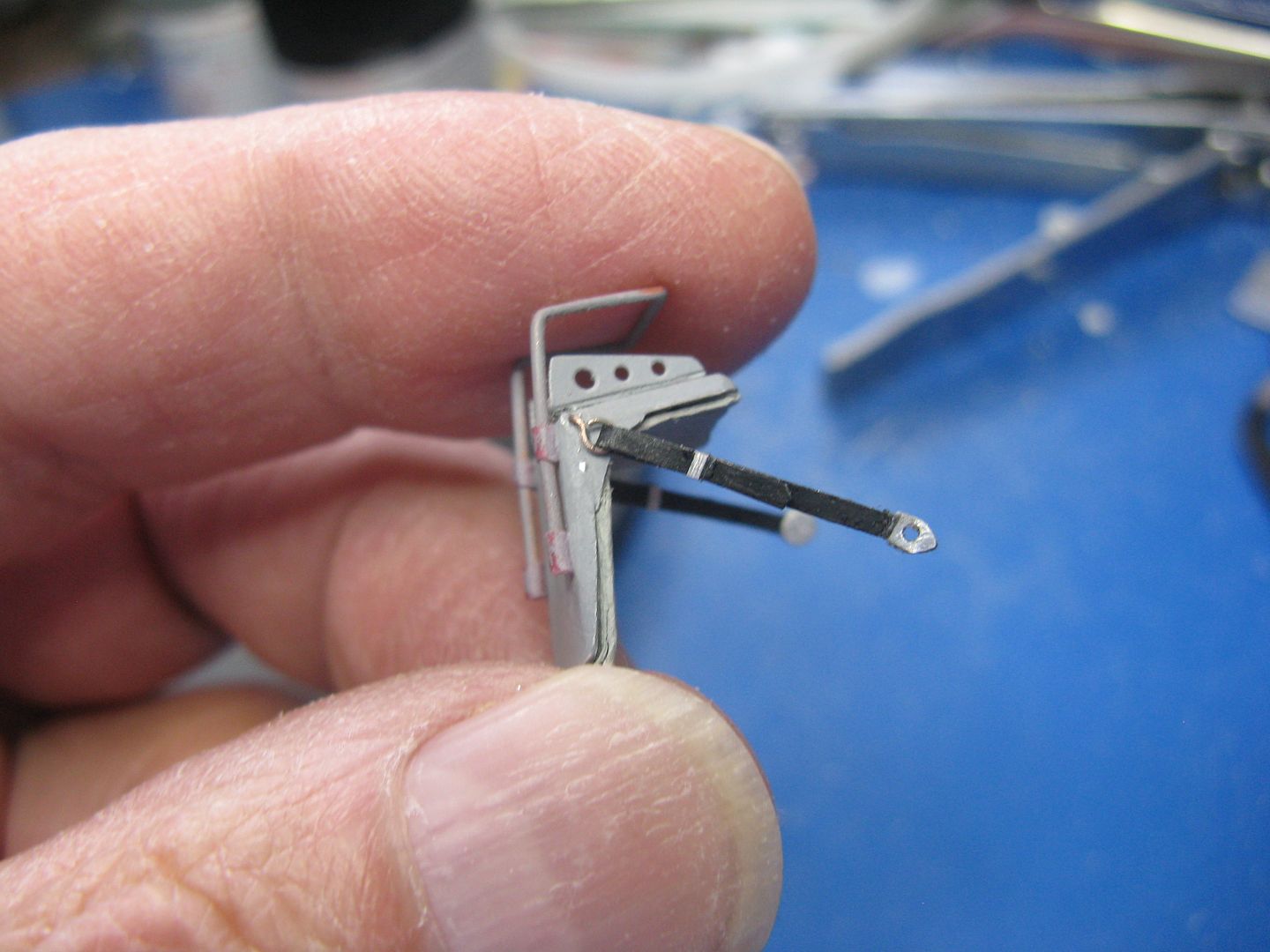
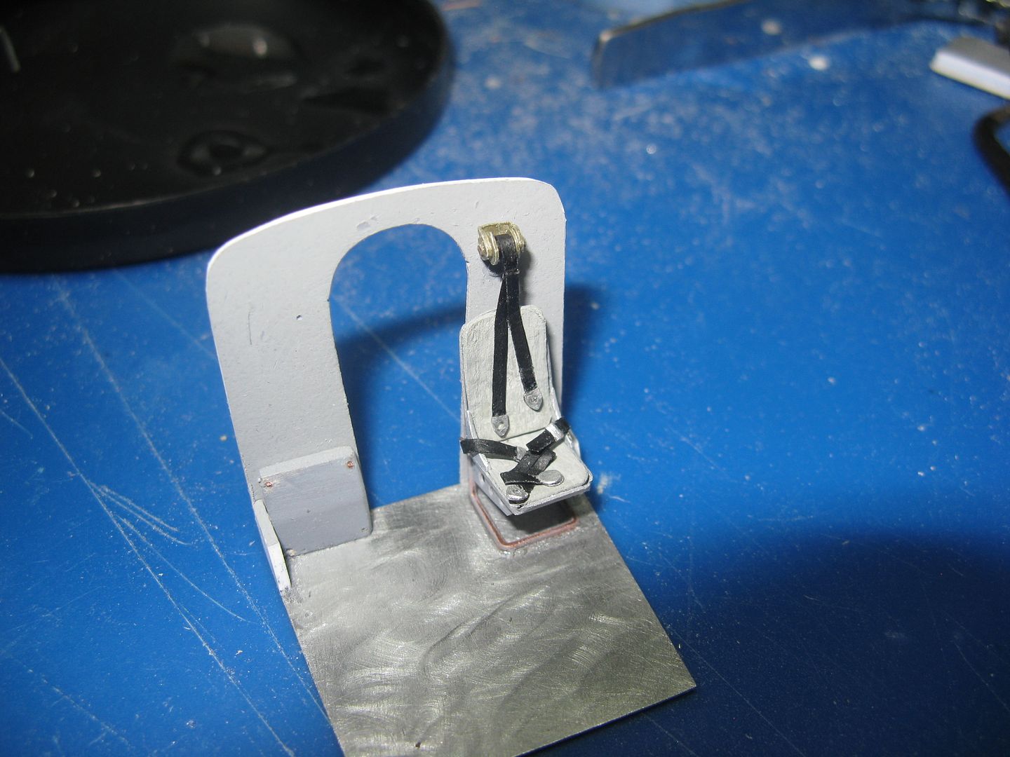
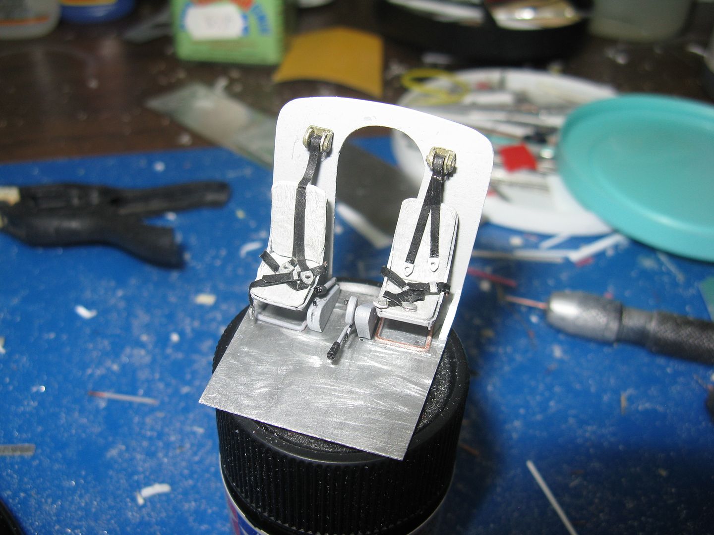
The end of the seat belt attachment fits into a little hole I had drilled in the seat support. One lap belt down, one to go.
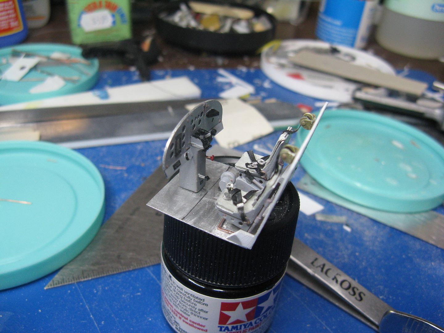
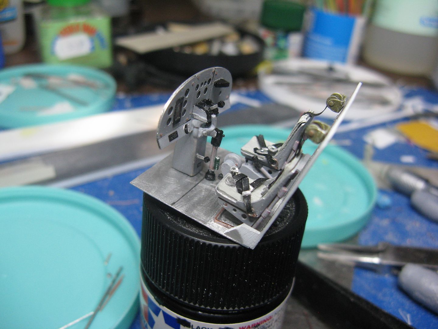
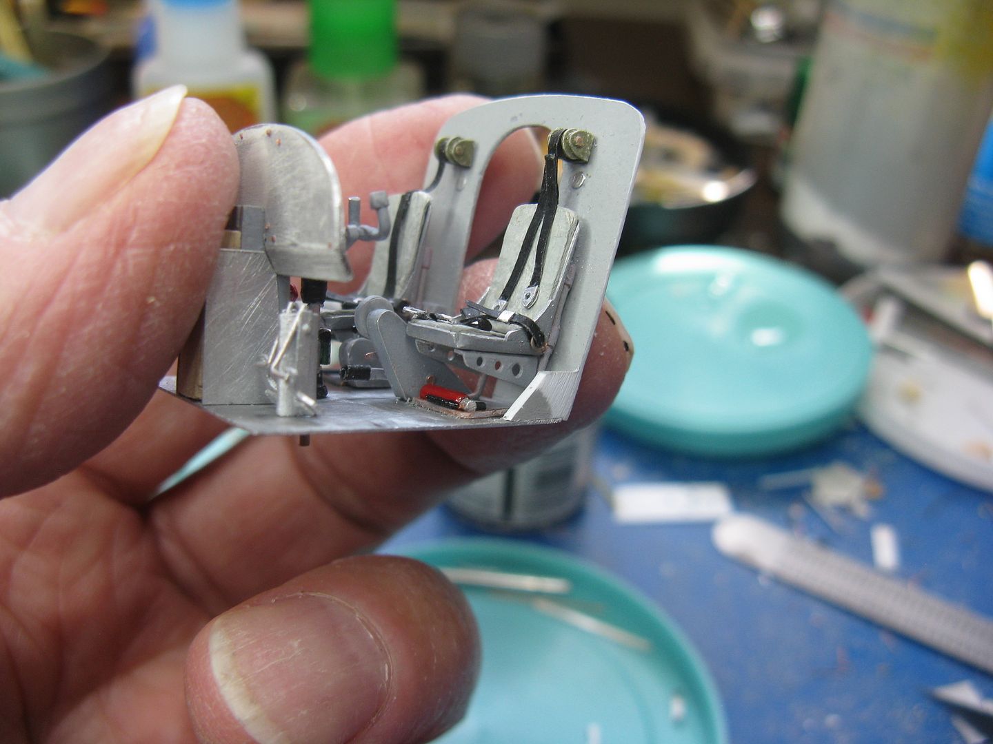
I made the inertia reels out of scrap metal and wire, then wound a couple of turns of belt material around the drum and glued it in place. I would have thought the reels would have been bare metal or black, but he who knows says they were olive drab.
Glue the reel to the cockpit bulkhead, make a shoulder harness from more belt material, glue the seat in place, then cut off the inertia belt to the right length and attach it to the shoulder harness. Viola! one down one to go.
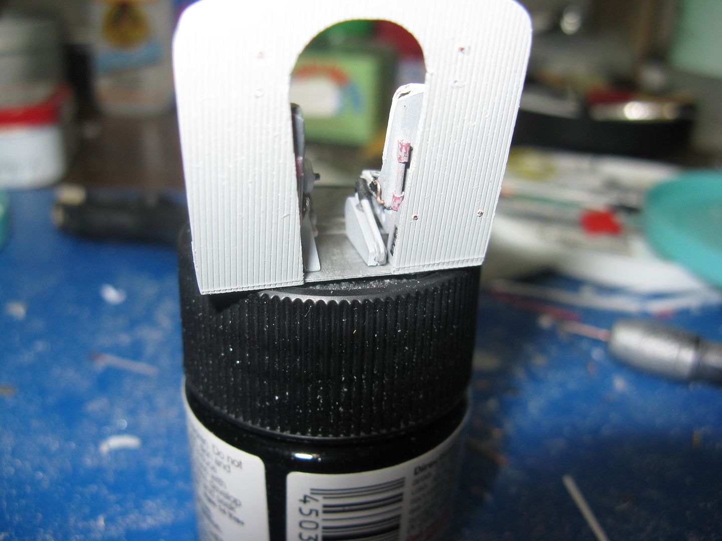
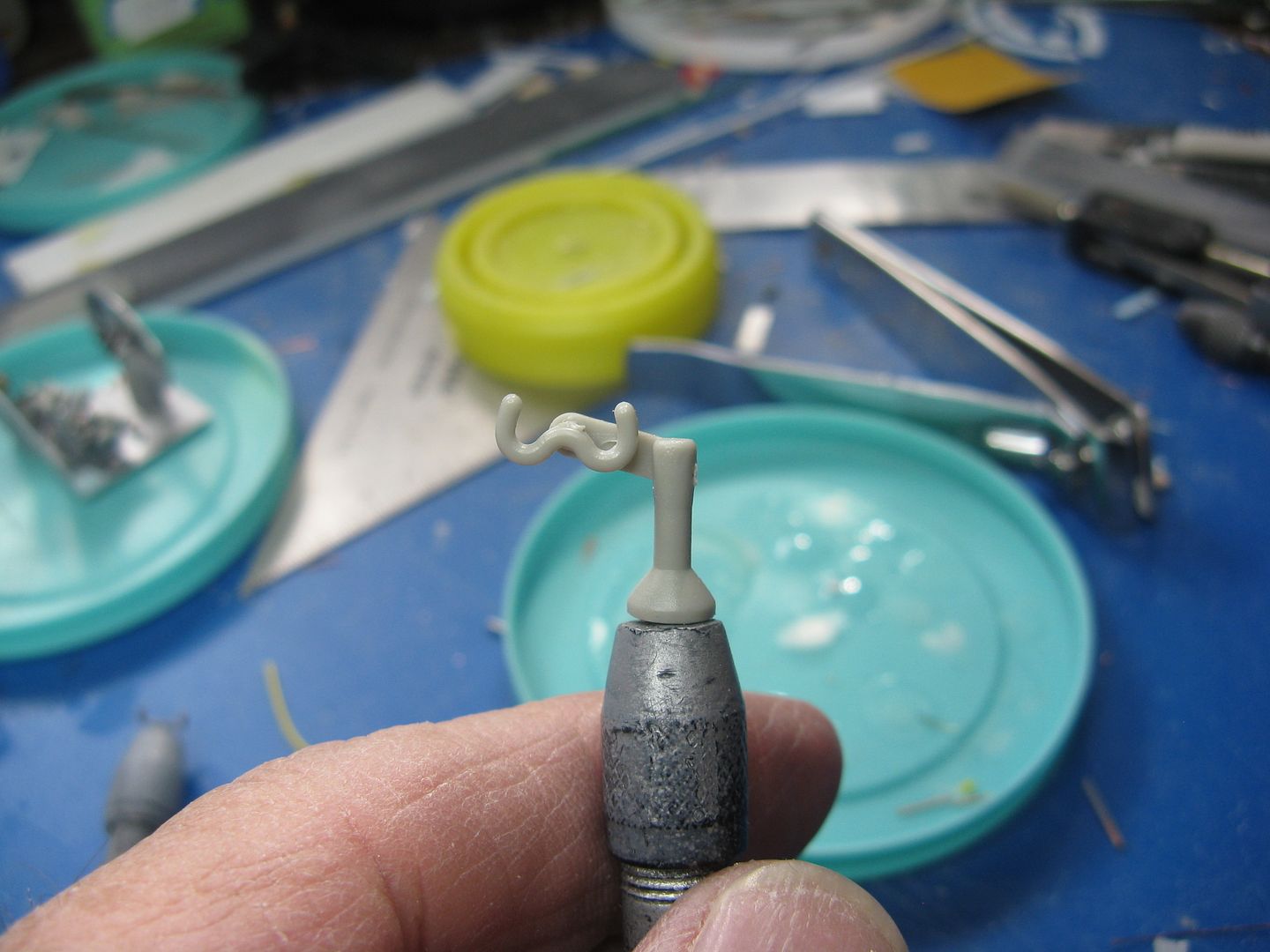
The flap pump, flap selector and the elevator trim wheel are all mounted on a console immediately to the right of the pilot's seat. I made the whole shebang from bits of wire and plastic. Looks like Zorg from the planet Tharg. Greetings Earthling, shake? I had to cut the end off the flap pump handle and the flap selector, it was simply too long. I did that after gluing the thing to the cockpit floor, so the pic doesn't do it adequate justice.
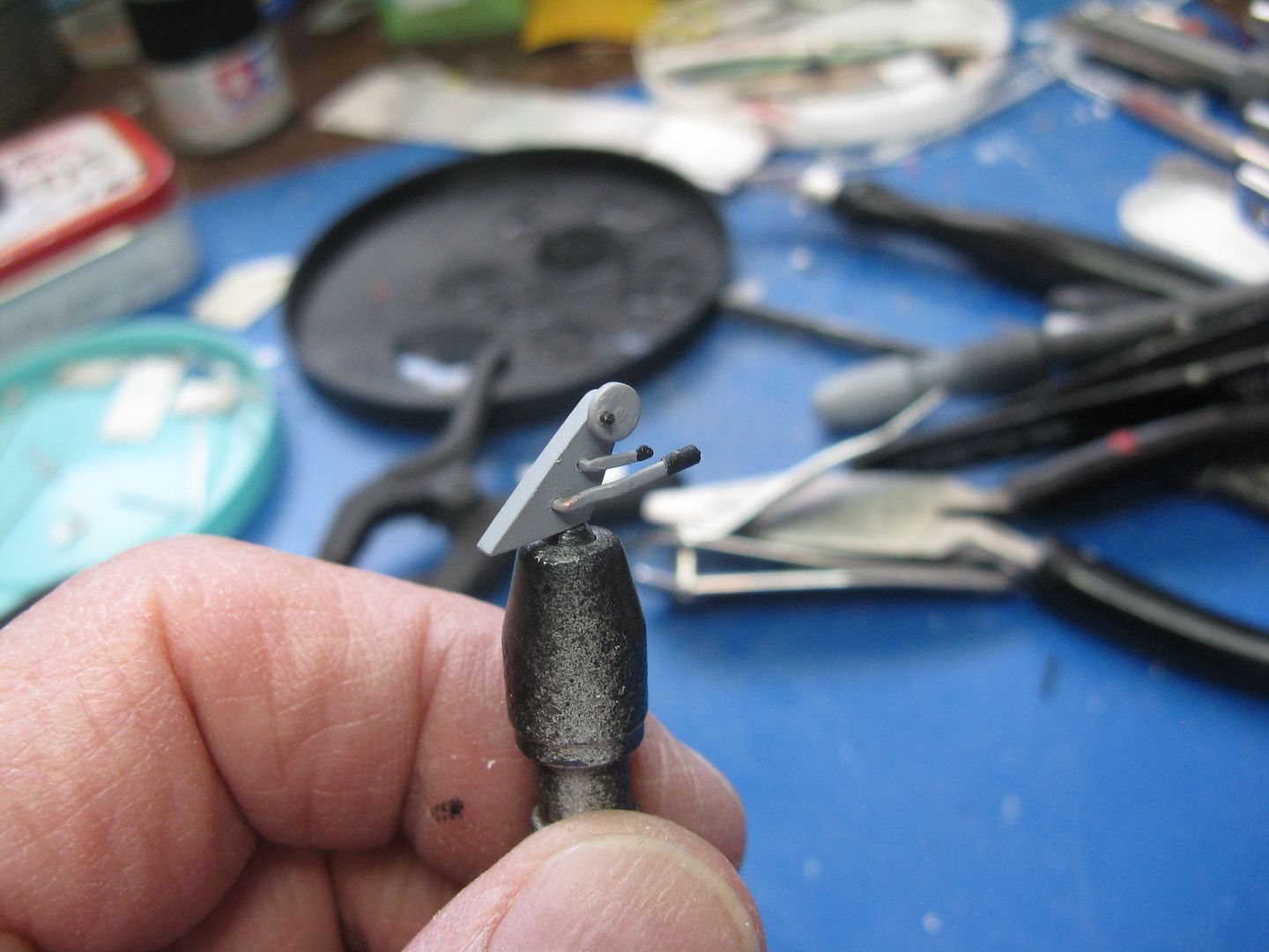
Flap and trim console in place.
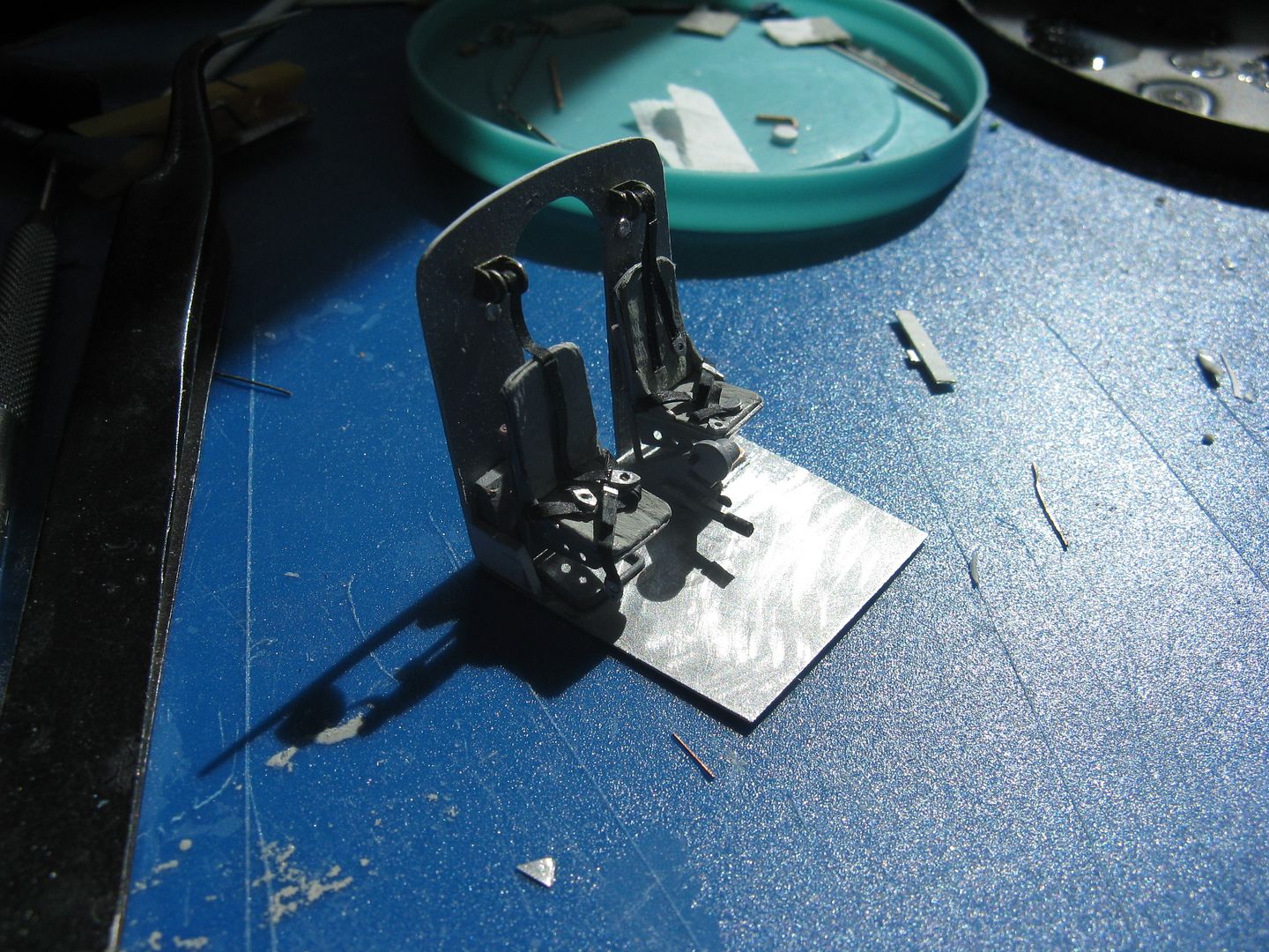
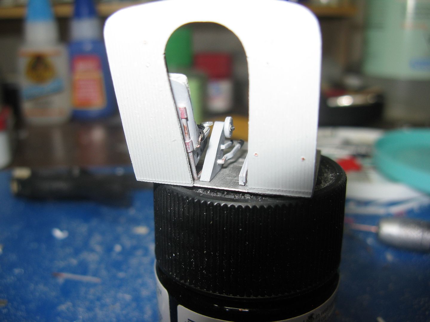
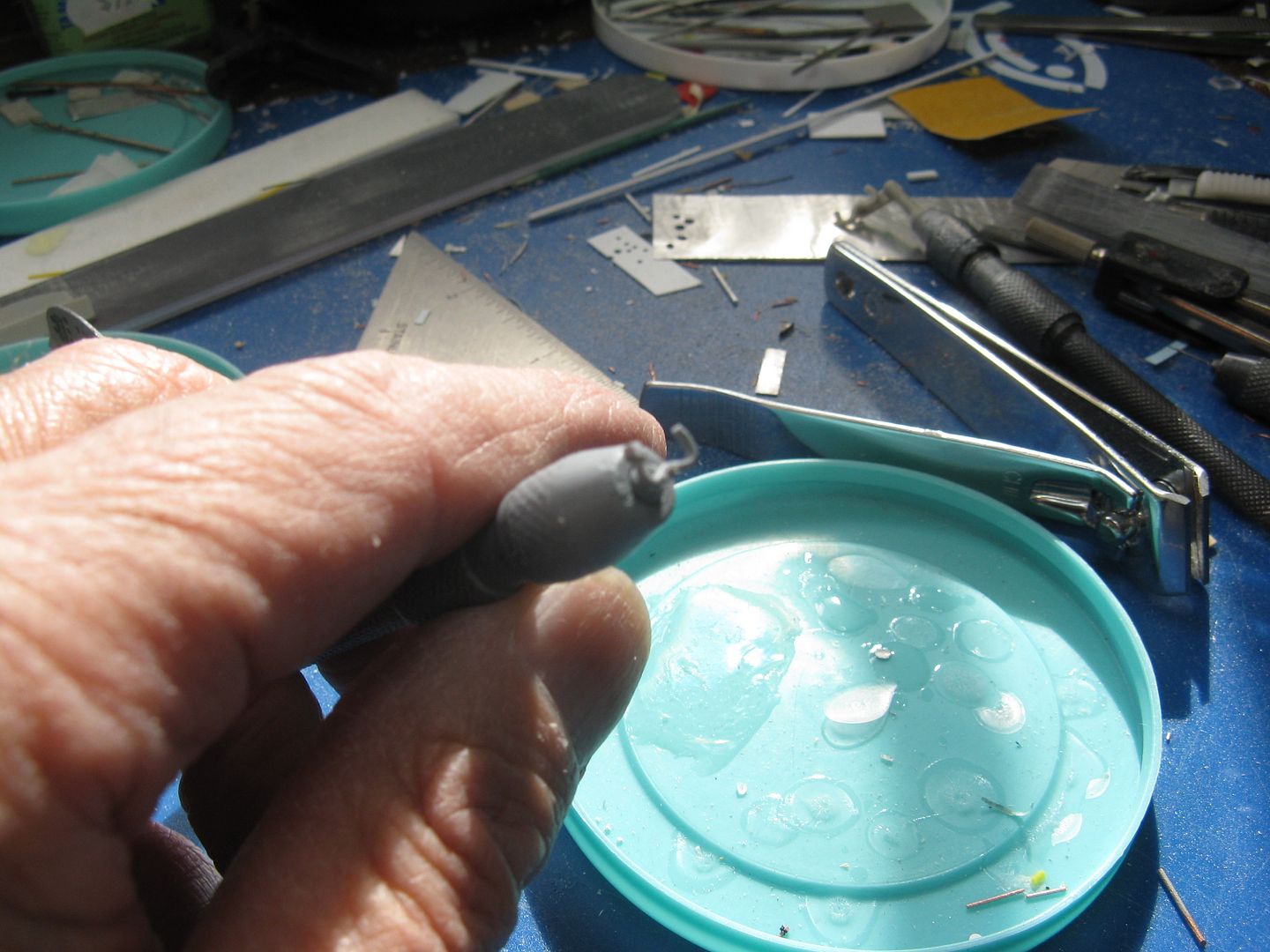
The airplane is equipped with deHavilland wheel skis. They can be selected down and will be 'blown' down by a pre-charged nitrogen cylinder attached to the ski itself, but they must be pumped up manually, against that nitrogen pre charge. The ski pump is located to the immediate left of the RH cockpit seat. If the pilot has to pump them up, by the time ski season is finished he will have a right arm like Popeye's and a left one like Olive Oyl. Vice versa if a cockpit crewman - swamper - is carried. I made the ski pump from bits of wire and plastic.
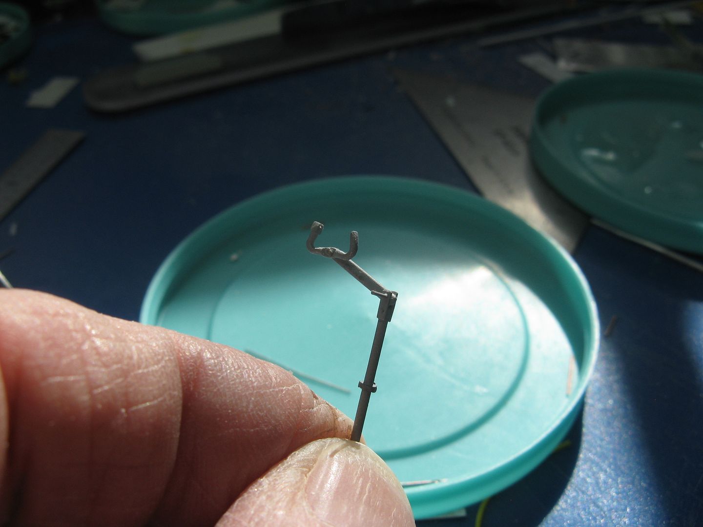
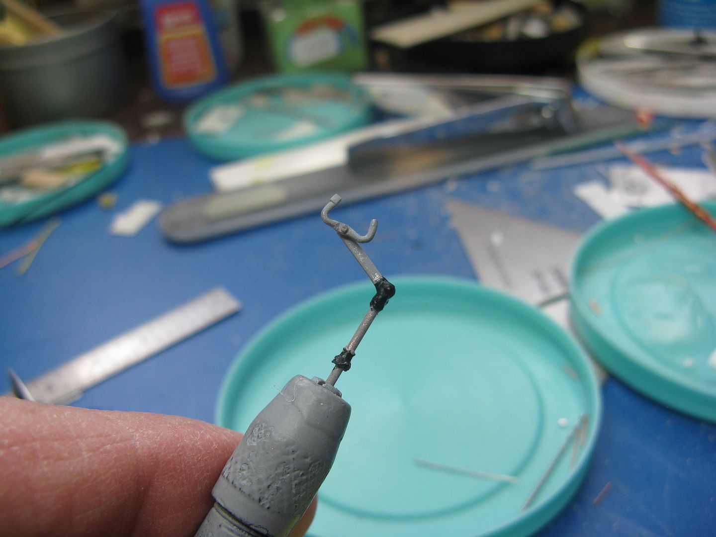
Ski pump in place.
And from a passenger's point of vue.
I have the instrument panel completed, will post more pix tomorrow.
Excellent corrections. Just out of curiosity, why didn't you just put in a strip of clear plastic (like that from a CD cover) into the slots you cut for the fuselage windows and then simply mask the clear areas?
Fair question, deserves a straight answer.
Mainly because I didn't think of it at the time, 'Course I could still do it, but I probably not. One, I like to use the kit windows, which will fit with minor modifications. The problem I have with using the strip of cd case would be the sanding and polishing and polishing and sanding required to achieve a job like Uros did on one of his models awhile back. I think it's probably six of one and half a dozen of the other, with the extra work required to remake the window openings being equal to the work required to sand and polish the one piece units. Also, when I install the headliner and cabin side panels I simply glue them to the inside of the cabin then cut the window openings out after the glue has dried.
For the seatbelts, I cut some Frog tape into strips of appropriate width, then painted them satin black. To attach them to the seats, I made some eyes by wrapping a short length of 28ga wire around a convenient pin...
...Cut off the excess wire...
...And bend the eye 90 degrees and slip the belt into the eye, making a loop.
The end of the seat belt attachment fits into a little hole I had drilled in the seat support. One lap belt down, one to go.
I made the inertia reels out of scrap metal and wire, then wound a couple of turns of belt material around the drum and glued it in place. I would have thought the reels would have been bare metal or black, but he who knows says they were olive drab.
Glue the reel to the cockpit bulkhead, make a shoulder harness from more belt material, glue the seat in place, then cut off the inertia belt to the right length and attach it to the shoulder harness. Viola! one down one to go.
The flap pump, flap selector and the elevator trim wheel are all mounted on a console immediately to the right of the pilot's seat. I made the whole shebang from bits of wire and plastic. Looks like Zorg from the planet Tharg. Greetings Earthling, shake? I had to cut the end off the flap pump handle and the flap selector, it was simply too long. I did that after gluing the thing to the cockpit floor, so the pic doesn't do it adequate justice.
Flap and trim console in place.
The airplane is equipped with deHavilland wheel skis. They can be selected down and will be 'blown' down by a pre-charged nitrogen cylinder attached to the ski itself, but they must be pumped up manually, against that nitrogen pre charge. The ski pump is located to the immediate left of the RH cockpit seat. If the pilot has to pump them up, by the time ski season is finished he will have a right arm like Popeye's and a left one like Olive Oyl. Vice versa if a cockpit crewman - swamper - is carried. I made the ski pump from bits of wire and plastic.
Ski pump in place.
And from a passenger's point of vue.
I have the instrument panel completed, will post more pix tomorrow.
nsmekanik
Member
I made the inertia reels out of scrap metal and wire, then wound a couple of turns of belt material around the drum and glued it in place. I would have thought the reels would have been bare metal or black, but he who knows says they were olive drab.
Glue the reel to the cockpit bulkhead, make a shoulder harness from more belt material, glue the seat in place, then cut off the inertia belt to the right length and attach it to the shoulder harness. Viola! one down one to go.
That looks like a good'n hefty noggin knocker to me :coolio just sayin.....

:drinks
phantom II
Master at Arms
Very nice update Be sure to wear a helmet 
Cheers, Christian B)
Be sure to wear a helmet Cheers, Christian B)

You should have seen where they were originally. I had 'em waaay too low, whiplash city, man. :woohoo:
Well, the night is still young and I'm so beautiful, I'll do the panel post now.
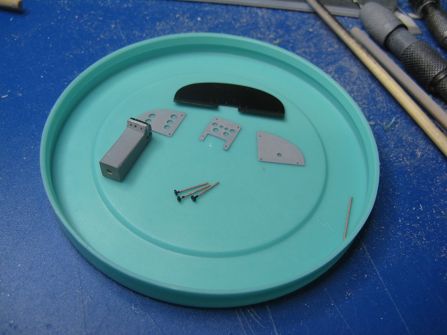
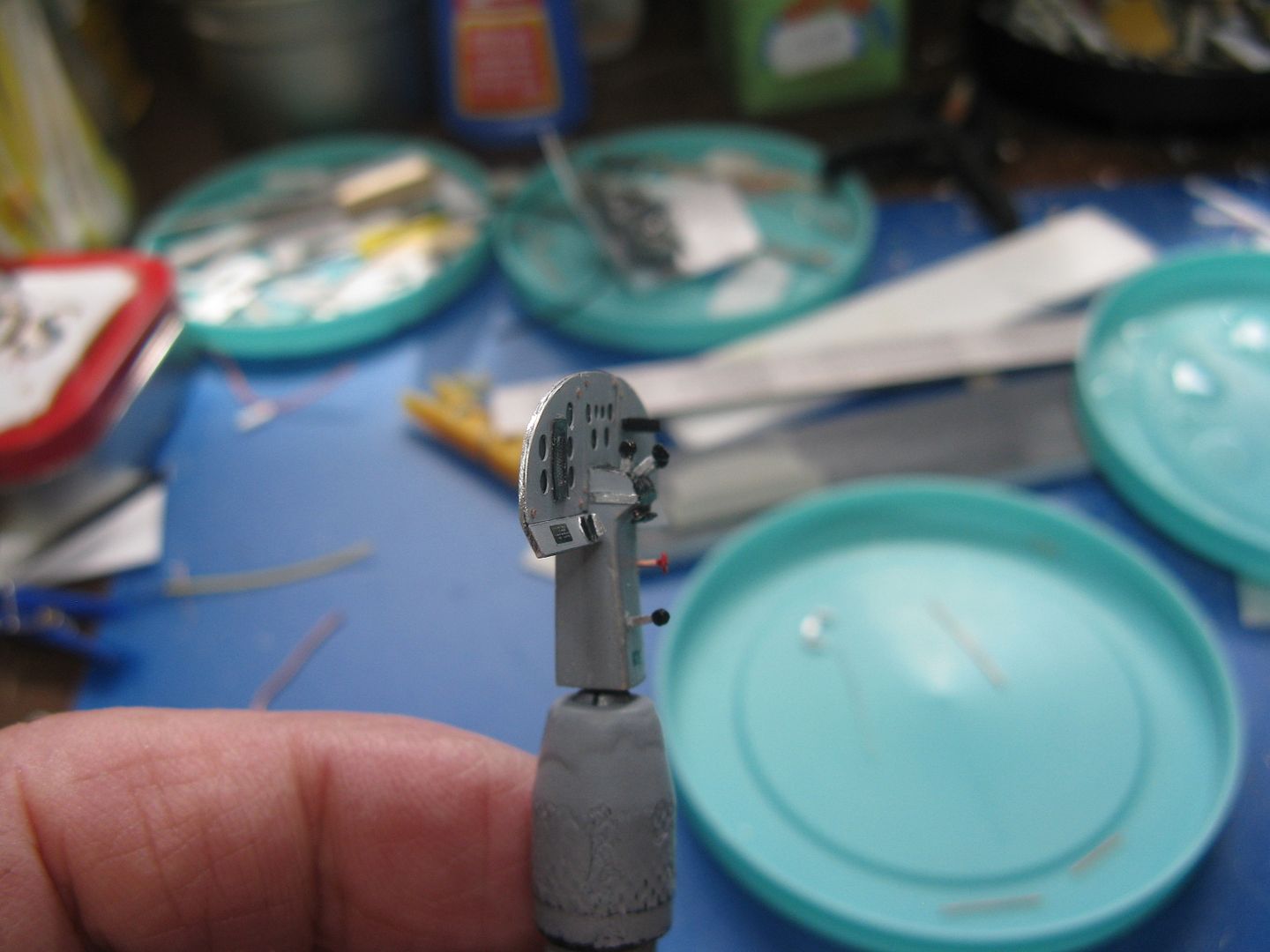
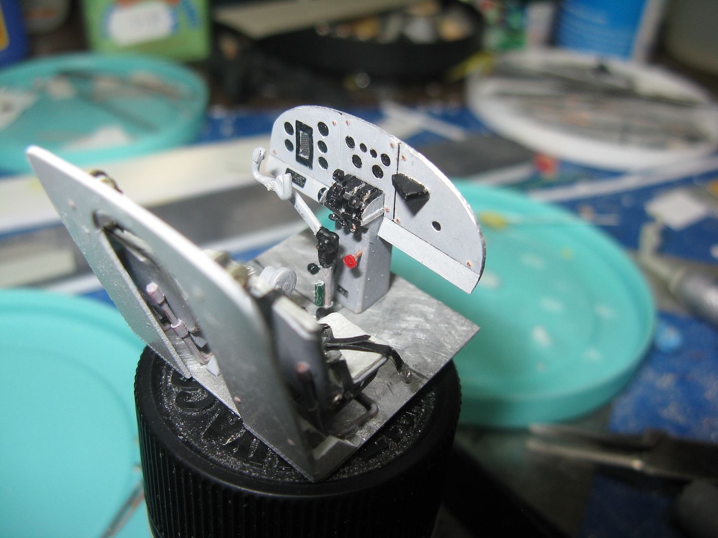
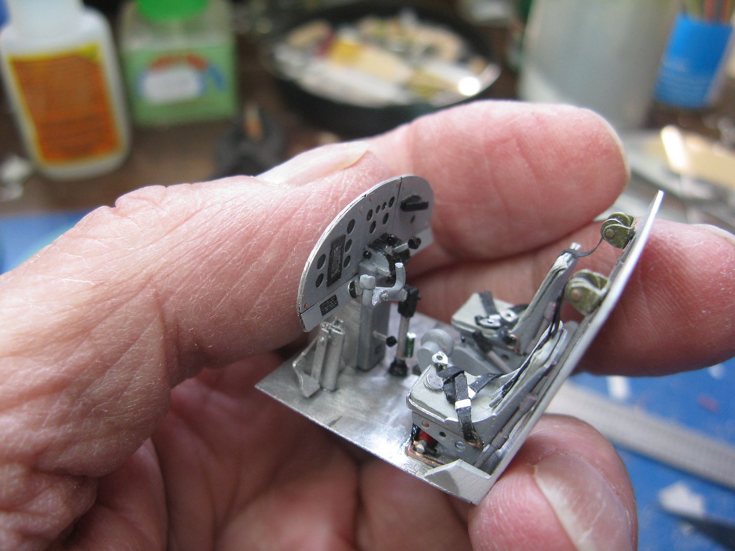
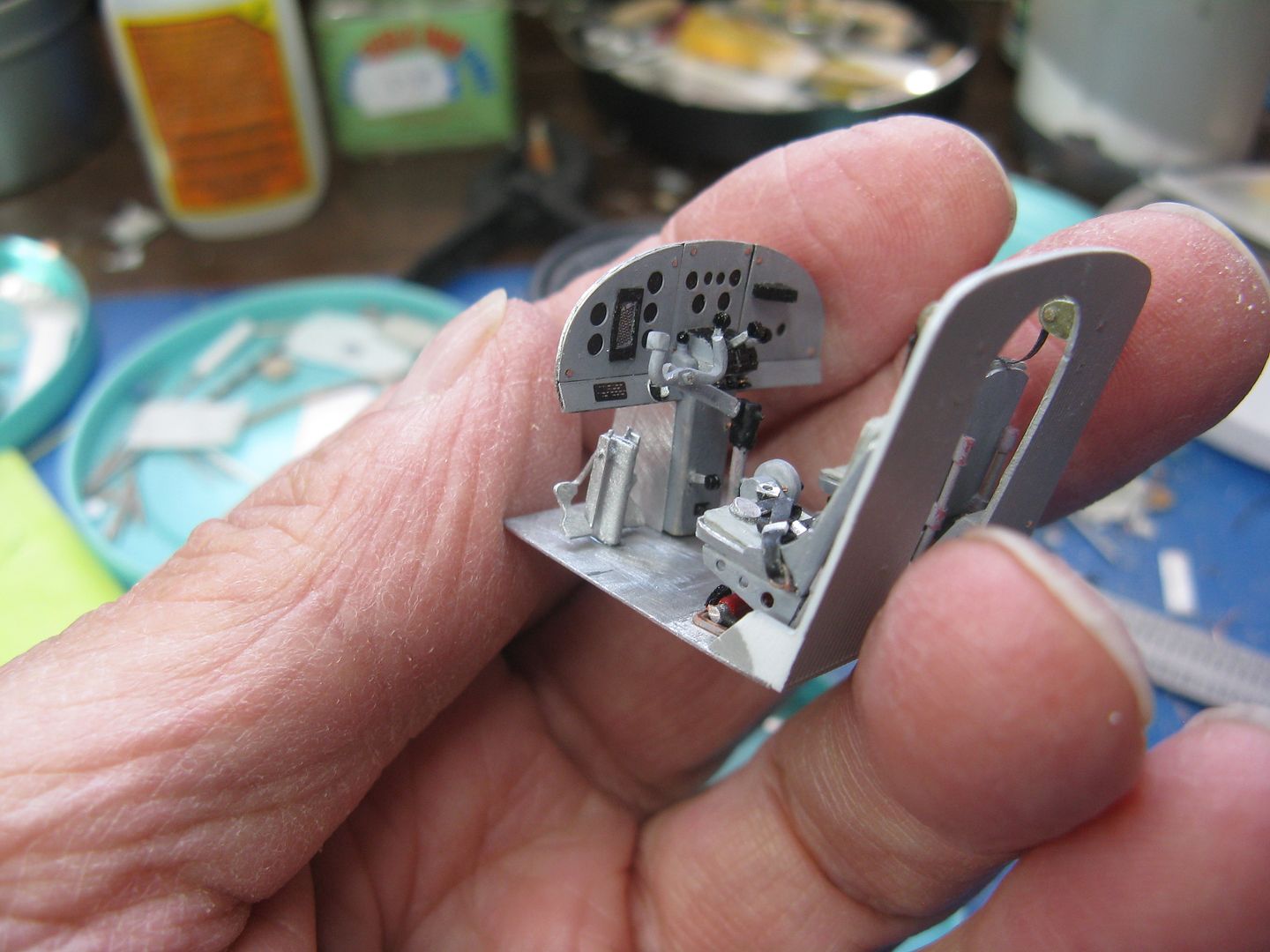
The instrument panel was made up of three sub panels. I made a backing panel from scrap metal and painted it black, then the three sub panels from beverage can, punched out holes for the instrument faces and painted it grey. The center pedestal containing what used to be the throttle, propeller and mixture control is from a bit of cedar shim. There are still three control levers there, but I have no idea what the third one would be for. Every turboprop I've ever flown - and I've got nearly 15,000 hours on t-props - only ever had two. The three little rounds on bits of wire are the engine control friction knobs.
The friction control knobs are in their place below their respective lever slots...
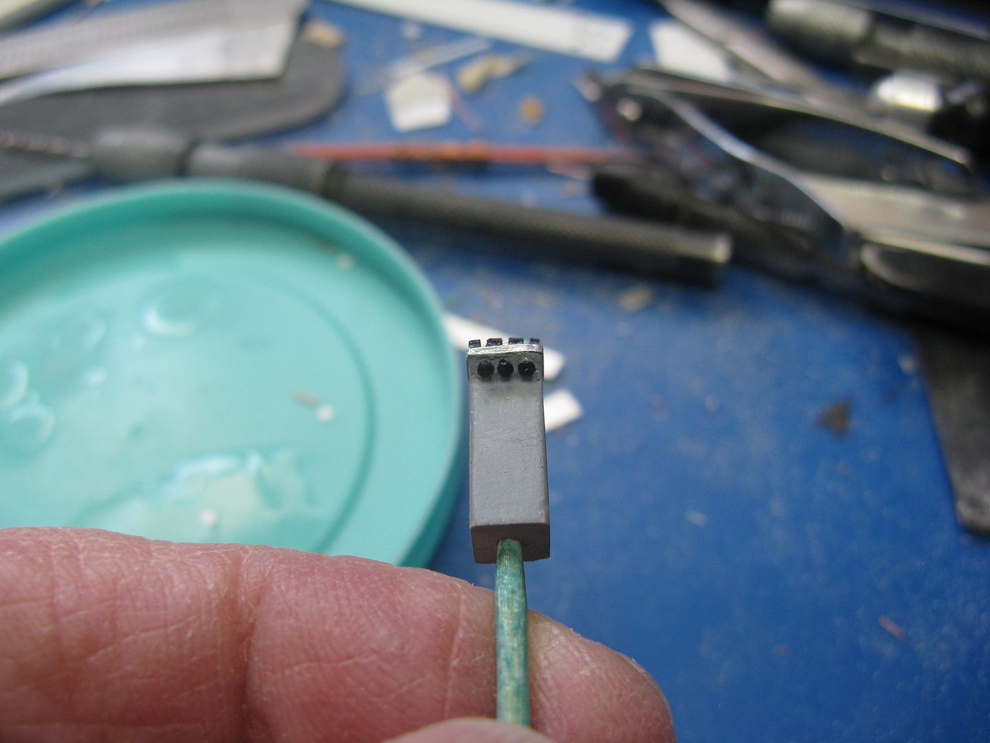
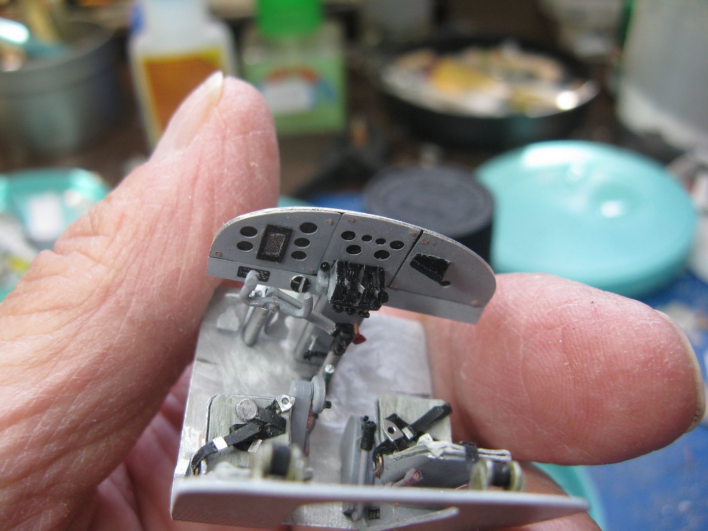
...And the panels have been joined and the whole thing slud down into the slot in the pedestal created for that purpose.
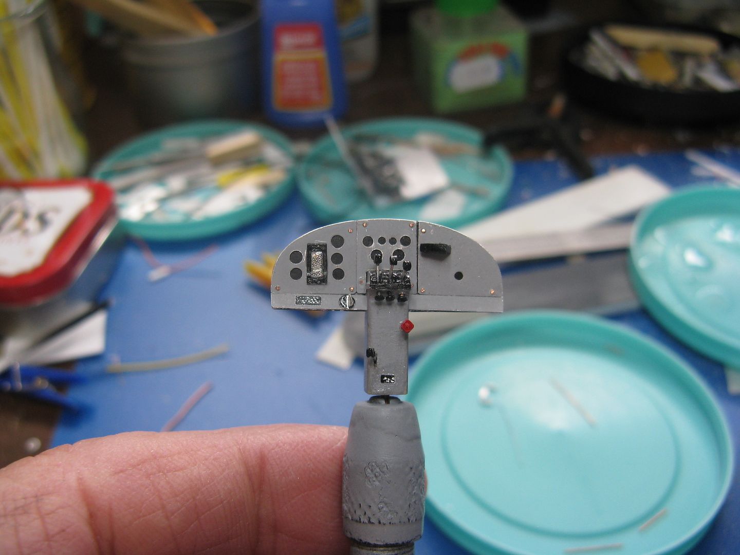
The engine controls are bits of scrap metal topped with tiny rounds of styrene pounded out with a Micro Mark punch. The red pull thingy is the emergency fuel and oil shutoff - or it used to be on the Stoneboat - and the lever on the lower left used to be the carburetor heat control. It's still there but I don't know what purpose it serves. I used some decal material to make a screen for that rectangular instrument in the left panel, it's probably a GPS readout or something. More decal material went for the switch panel on the left hand skirt panel, and the aircraft data plate on the lower pedestal
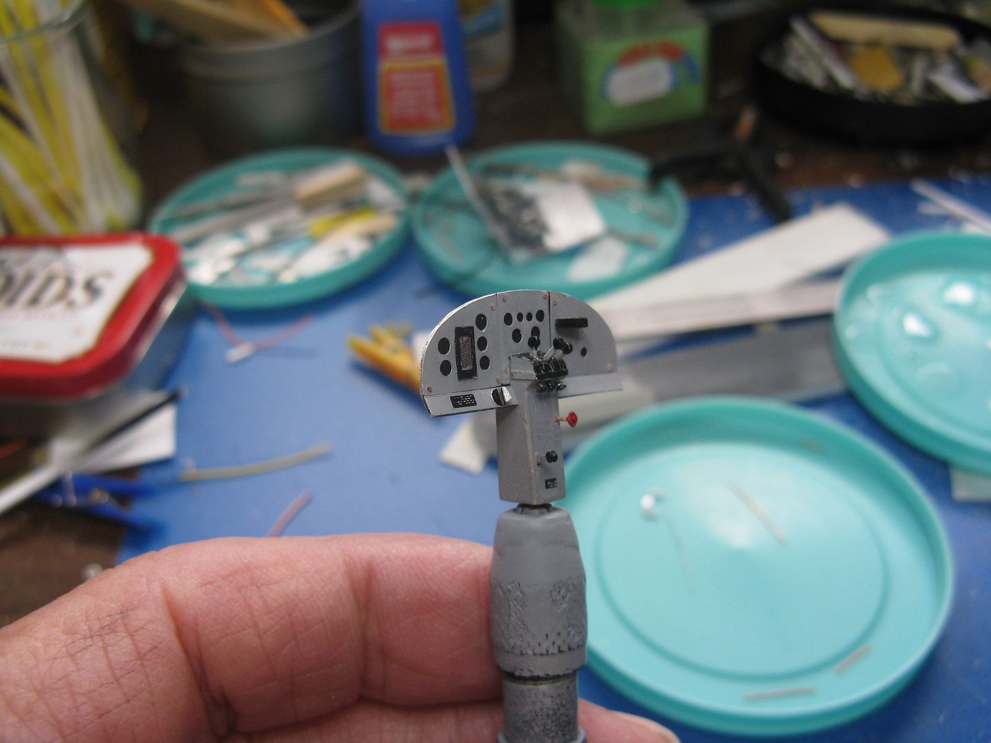
Everything has been attached to the cockpit floor, using epoxy.
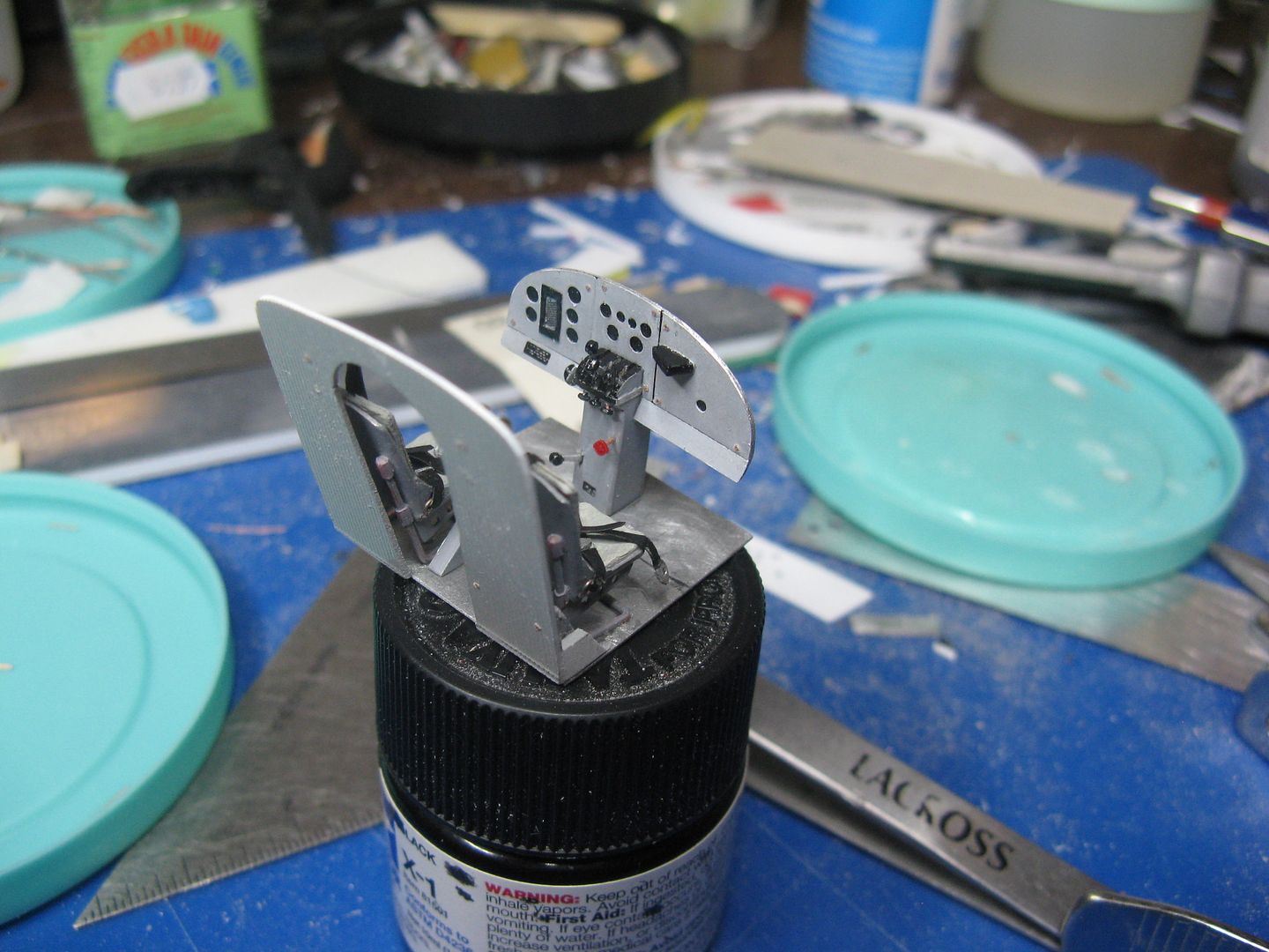
And by golly, it fits!
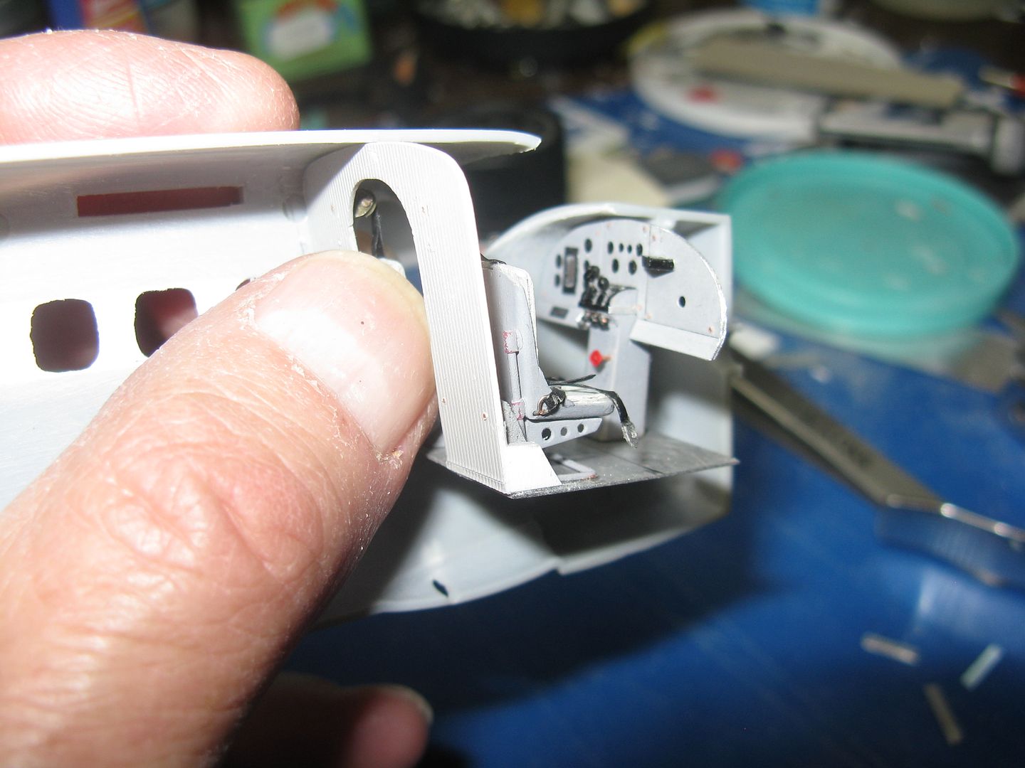
I gotta build the footwells, rudder pedals and of course a control yoke. Start that tomorrow.
Man, there's some kid on The Voice who just aced it, sang The Rising. Maybe not as good as the Boss, but pretty damn close.
Well, the night is still young and I'm so beautiful, I'll do the panel post now.
The instrument panel was made up of three sub panels. I made a backing panel from scrap metal and painted it black, then the three sub panels from beverage can, punched out holes for the instrument faces and painted it grey. The center pedestal containing what used to be the throttle, propeller and mixture control is from a bit of cedar shim. There are still three control levers there, but I have no idea what the third one would be for. Every turboprop I've ever flown - and I've got nearly 15,000 hours on t-props - only ever had two. The three little rounds on bits of wire are the engine control friction knobs.
The friction control knobs are in their place below their respective lever slots...
...And the panels have been joined and the whole thing slud down into the slot in the pedestal created for that purpose.
The engine controls are bits of scrap metal topped with tiny rounds of styrene pounded out with a Micro Mark punch. The red pull thingy is the emergency fuel and oil shutoff - or it used to be on the Stoneboat - and the lever on the lower left used to be the carburetor heat control. It's still there but I don't know what purpose it serves. I used some decal material to make a screen for that rectangular instrument in the left panel, it's probably a GPS readout or something. More decal material went for the switch panel on the left hand skirt panel, and the aircraft data plate on the lower pedestal
Everything has been attached to the cockpit floor, using epoxy.
And by golly, it fits!
I gotta build the footwells, rudder pedals and of course a control yoke. Start that tomorrow.
Man, there's some kid on The Voice who just aced it, sang The Rising. Maybe not as good as the Boss, but pretty damn close.
No Multifunction display or computer interface? 
why I bet they even had an ashtray in that panel somewhere.
Looks swell
why I bet they even had an ashtray in that panel somewhere.
Looks swell
Duke Maddog
Well-known member
Oh wow! I never would have imagined using all that to do those details. Man, I am such a basic, nothing modeler compared to all this! What stunning work, words fail me....
Thanks for the kind comments fellas.
'Dog, don't sell yourself short buddy. I been building those Otters since Pontius was a pilot - eight or ten of them for sure - and I have flown the airplane so I know where all the bodies are buried, metaphorically speaking. Plus, I'm retired and it keeps me out of the bar.ldguy
The ashtray was mounted on the control column a foot or so above the floor. It was a cylindrical affair, the size of a beer can, even had its own mounting clip. Of course from time to time they must be emptied, at which point many were lost overboard and were replaced with the aforementioned beer can, held in place with duct tape...why I bet they even had an ashtray in that panel somewhere.
'Dog, don't sell yourself short buddy. I been building those Otters since Pontius was a pilot - eight or ten of them for sure - and I have flown the airplane so I know where all the bodies are buried, metaphorically speaking. Plus, I'm retired and it keeps me out of the bar.
ldguyDuke Maddog
Well-known member
Thanks 'boat! It sure does show in your work.
Welp, stick a fork in the cockpit, I'm calling it done.
A one holer poler must have a proper pole with which to pole the one holer, not this abortion from the kit...hmy:
...So I cobbled one together from bits of wire. A new yoke, complete with the little square PTT switch on the left horn...
...And the column from wire and bits of scrap aluminum.
To replicate the rubber boot where the column goes through the cockpit floor and the boot over the throw-over mechanism, I simply slopped some white glue where needed and painted it black when the glue dried.
Ashtray!! A bit of aluminum wire painted green and then a couple of swipes with a sanding stick to remove a bit of paint, and that is as close as yer gonna get to a Labatt 50 can in that scale.
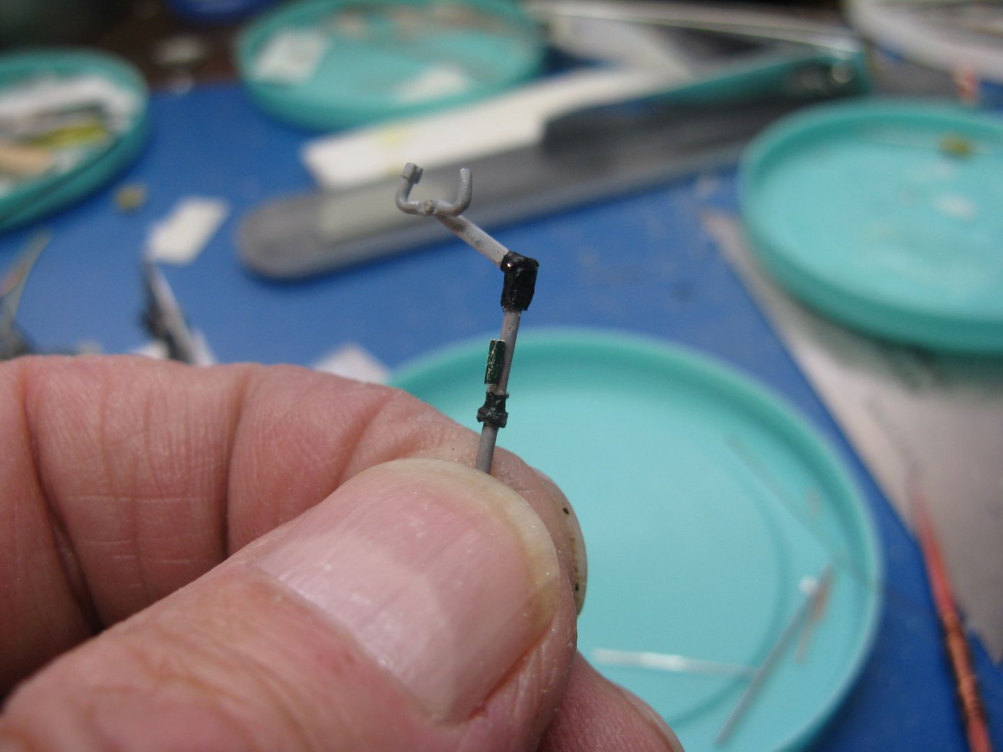
The new pole - complete with beer can ashtray - is now in place.
There's a little sub assembly attached to the left side of the throttle quadrant that has a small lever with a black knob on the end sticking out of it. I don't know what purpose it serves, there was nothing like this on the Stoneboat. I hope it isn't some kind of electric ski pump, because that will mean I have shamed both Popeye and Olive Oyl for nothing. I made one anyway as well as a coclpit fire extinguisher from bits of wire and plastic...

...Stuck the unknown part to the throttle quadrant...
...And the extinguisher underneath the seat pilot's seat.
I made a set of rudder/brake pedals from scarp aluminum and wire, and glued them in place in the LH footwell.
And that's where she stands, I'm calling the cockpit complete. Next up will be the cabin, beginning with a new metal floor.
A one holer poler must have a proper pole with which to pole the one holer, not this abortion from the kit...
hmy:
...So I cobbled one together from bits of wire. A new yoke, complete with the little square PTT switch on the left horn...
...And the column from wire and bits of scrap aluminum.
To replicate the rubber boot where the column goes through the cockpit floor and the boot over the throw-over mechanism, I simply slopped some white glue where needed and painted it black when the glue dried.
Ashtray!! A bit of aluminum wire painted green and then a couple of swipes with a sanding stick to remove a bit of paint, and that is as close as yer gonna get to a Labatt 50 can in that scale.
The new pole - complete with beer can ashtray - is now in place.
There's a little sub assembly attached to the left side of the throttle quadrant that has a small lever with a black knob on the end sticking out of it. I don't know what purpose it serves, there was nothing like this on the Stoneboat. I hope it isn't some kind of electric ski pump, because that will mean I have shamed both Popeye and Olive Oyl for nothing. I made one anyway as well as a coclpit fire extinguisher from bits of wire and plastic...
...Stuck the unknown part to the throttle quadrant...
...And the extinguisher underneath the seat pilot's seat.
I made a set of rudder/brake pedals from scarp aluminum and wire, and glued them in place in the LH footwell.
And that's where she stands, I'm calling the cockpit complete. Next up will be the cabin, beginning with a new metal floor.