
jeaton01
Well-known member
This is one I started a few months ago while proceeding slowly with an early B-26 conversion, thinking it would be a quick build, but that has not been so. No fault of the Tamiya kit that is used as the basis, but the KMC set to be used turned out to require a lot of work because it had some poor guidance.
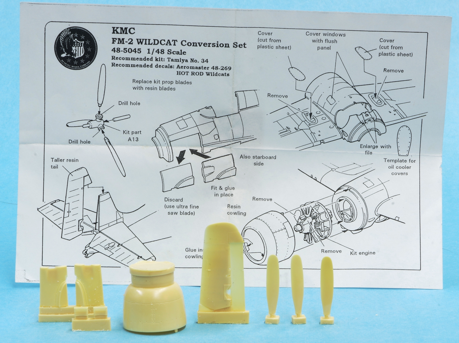
The KMC conversion parts and instructions. The rudder needed modification as the aerodynamic counterbalance came down too far. The lower part was cut off and attached to the fin so that it looked more like photos to me. I didn't use the cowl except as a guide for positioning the cowl flaps, which caused trouble because they were too low on the cowl and did not align with the exhaust depressions. The cowl didn't fit the Tamiya kit very well. They tell you to put inlet ducts in the bottom of the cowl which is not accurate for the FM-2. They do tell you to remove the magnetos from the kit engine but you are still left with the wrong number of cylinders and incorrect nose section.
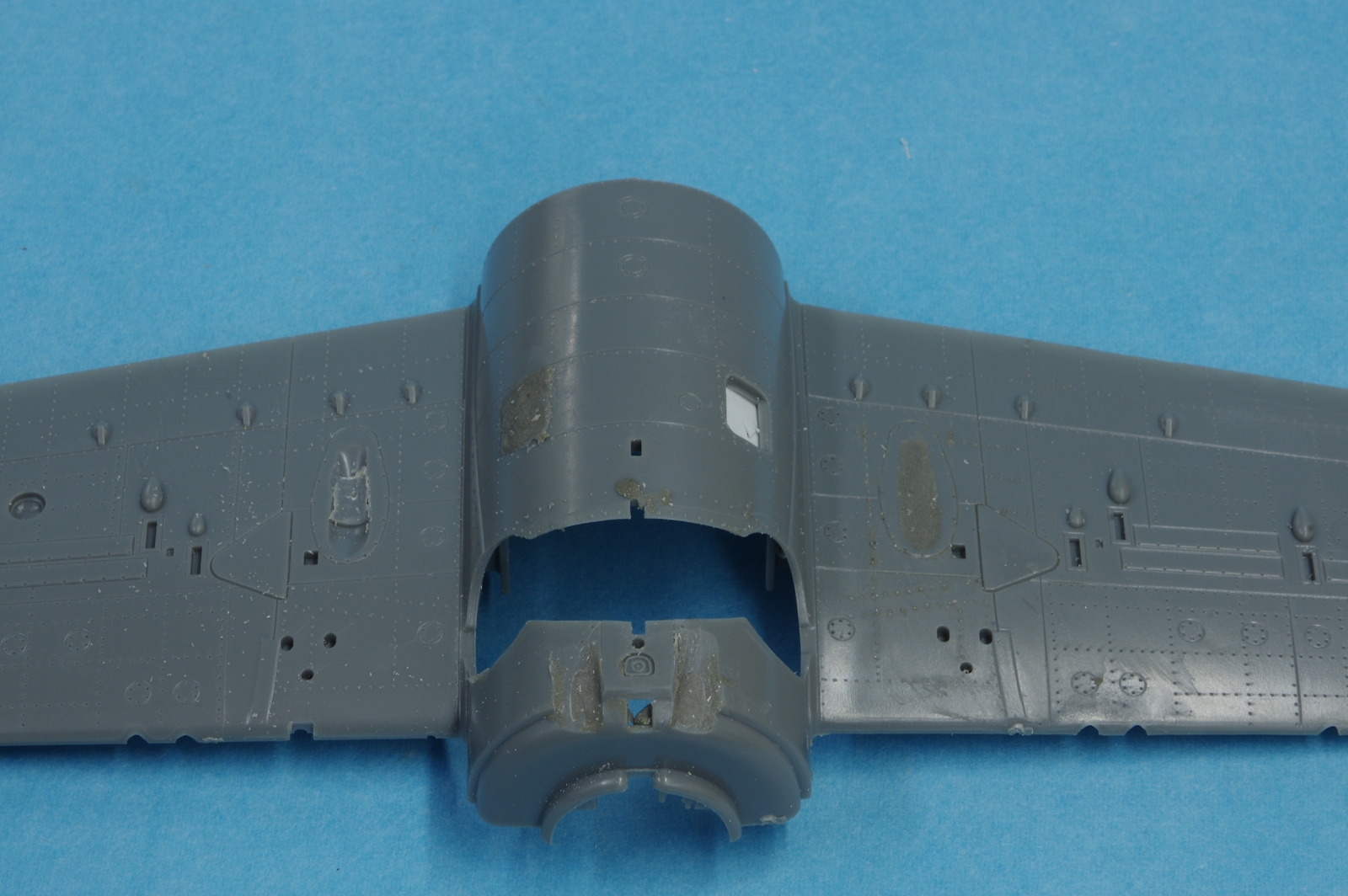
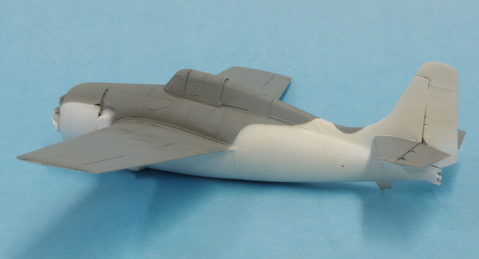
The FM-2 had metal plates where the lower fuselage window were on earlier Wildcats so they were backed with plastic card and filled with Epoxysculpt. The oil cooler was behind the engine in the accessory compartment so the remnants of the wing oil coolers were ground away and the remaining depressions filled with Epoxysculpt as well. The FM-2 had two exhaust stacks on the bottom like the earlier Wildcats but they were smaller and under the cowl with larger reliefs into the fuselage behind the cowl. More grinding and filling. Since the FM-2 had no outboard guns the accompanying shell chutes and bulges, ammunition loading doors below and gun access doors on top of the wings must be removed where the outboard guns were on the F4F-4 and FM-1.
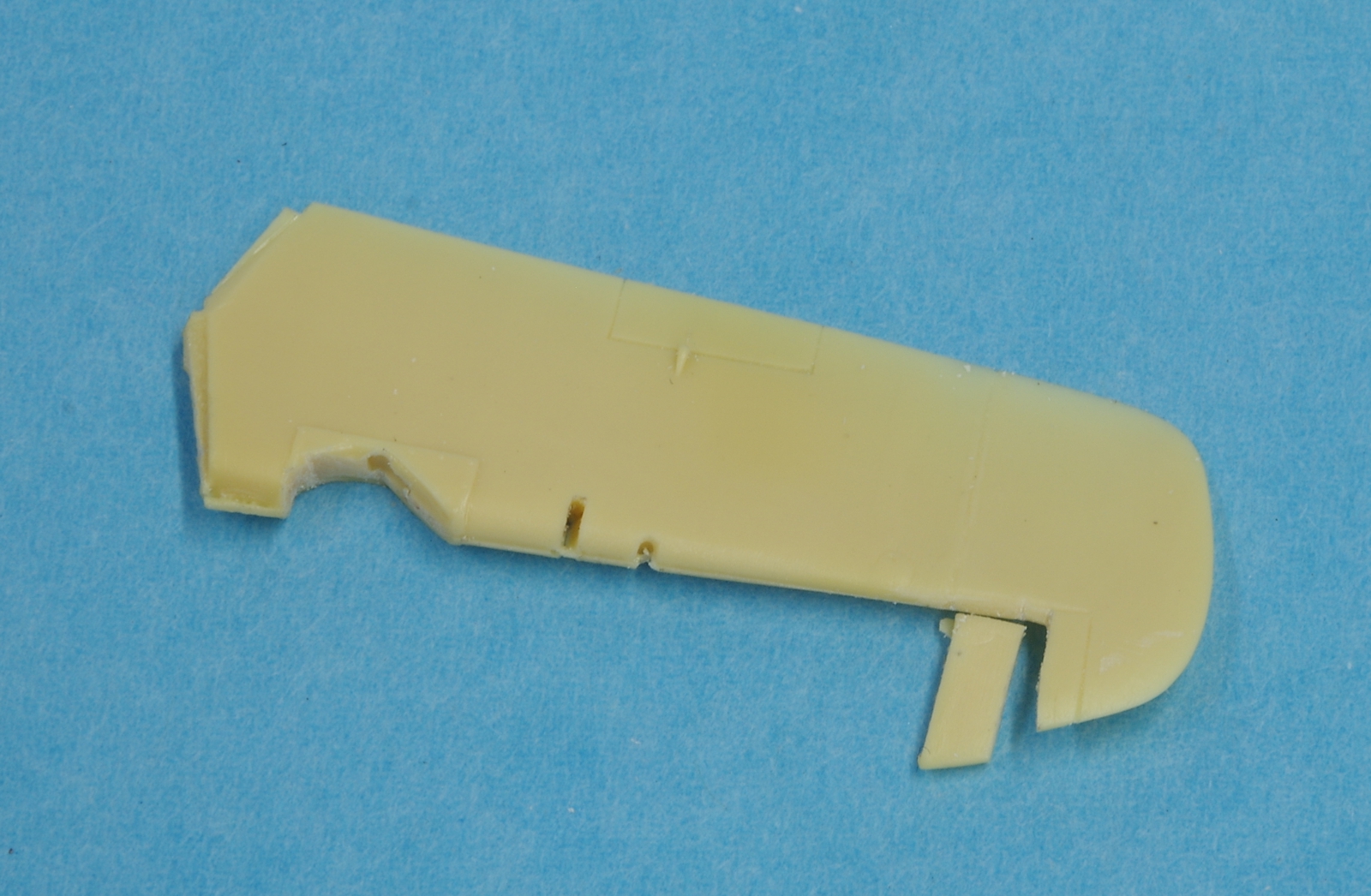
The change to the KMC FM-2 rudder.
Epoxysculpt was used to fill in behind the KMC exhaust reliefs as they were too shallow to allow representation of the exhaust pipes under the cowl sides. It was also used to modify the propeller hub, although for many FM-2's the Tamiya hub would be correct.
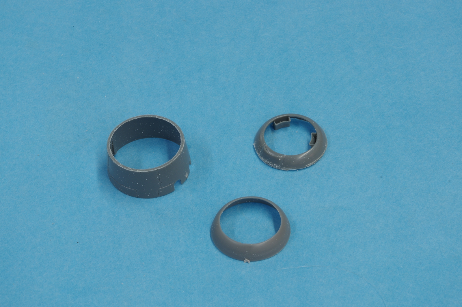
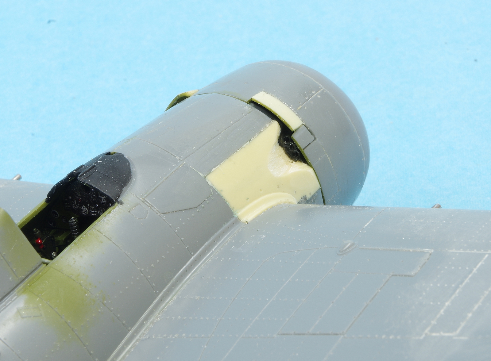
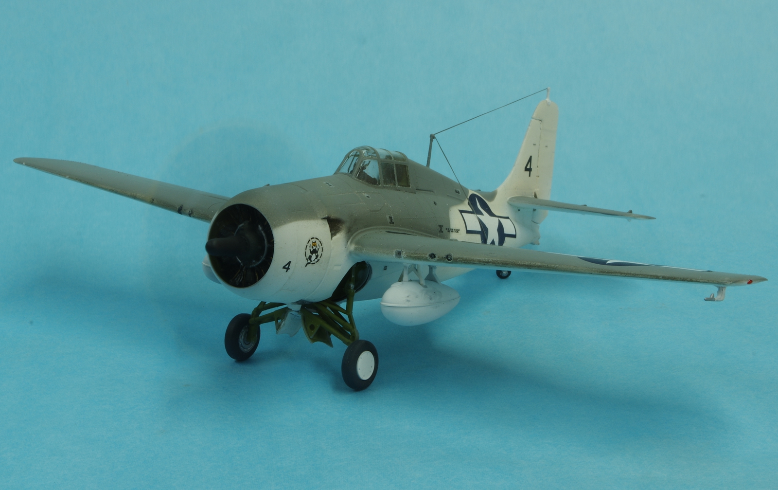
The front cowl ring from the Sword FM-2 was adapted to the Tamiya cowl.
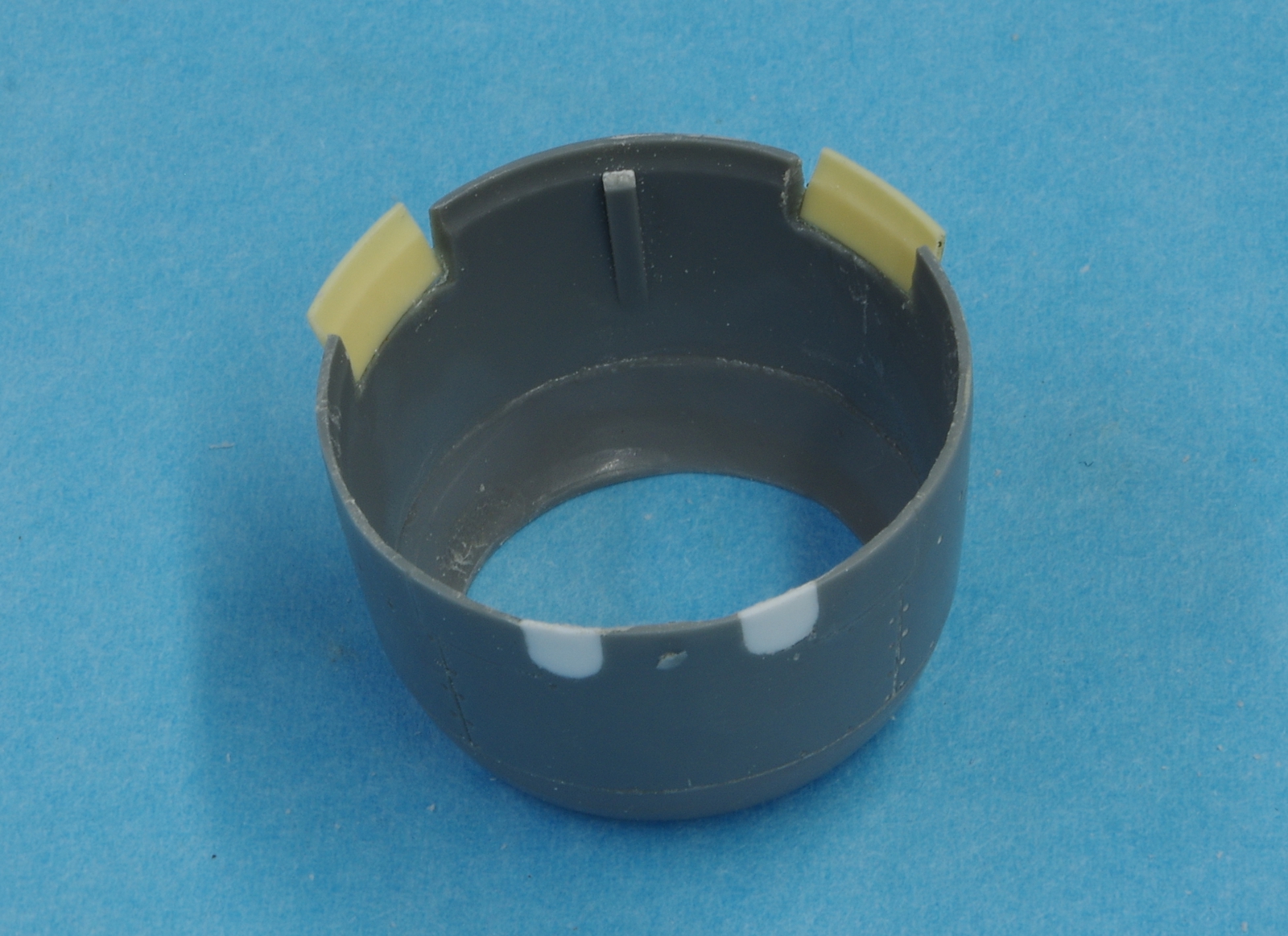
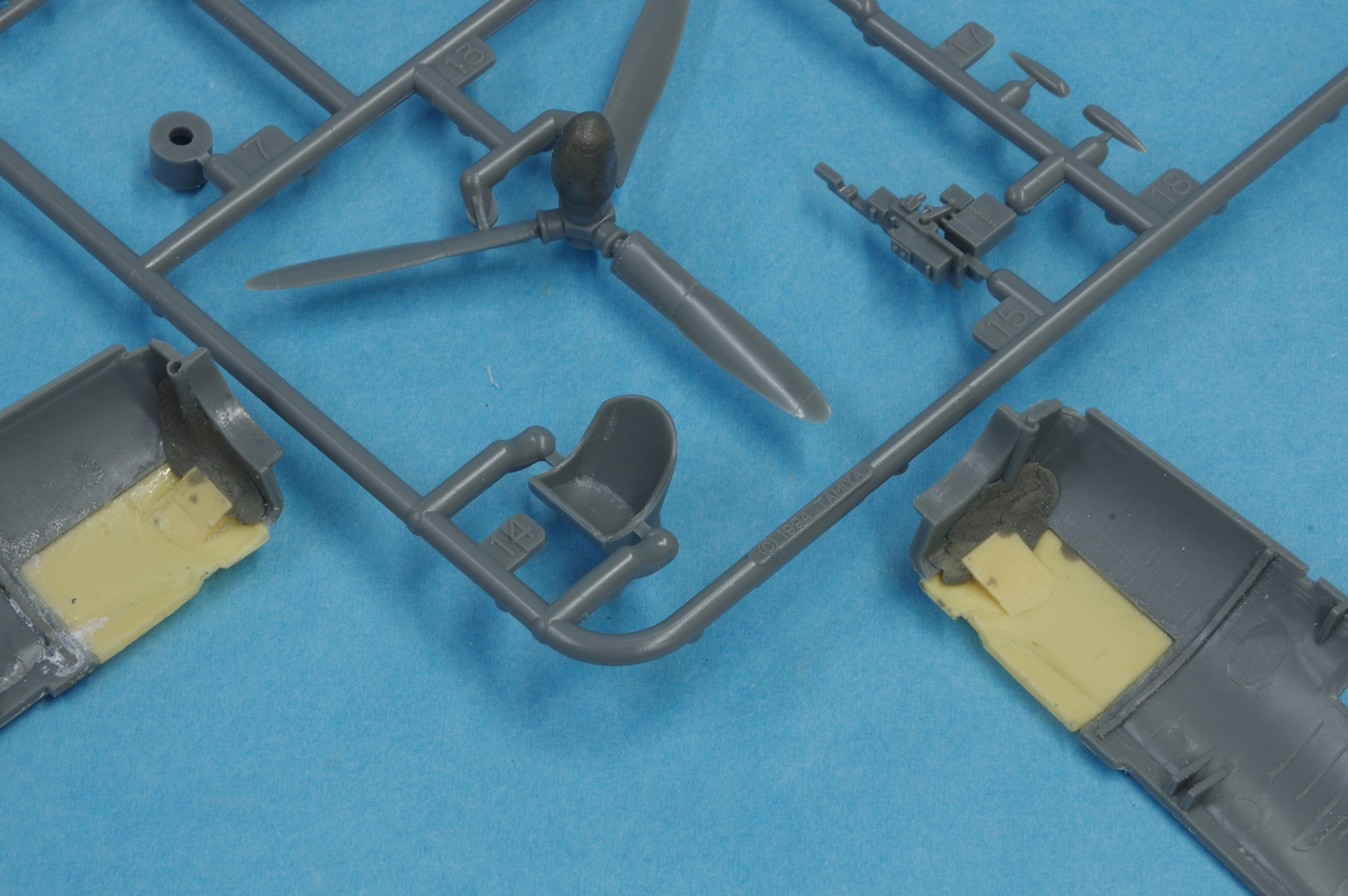
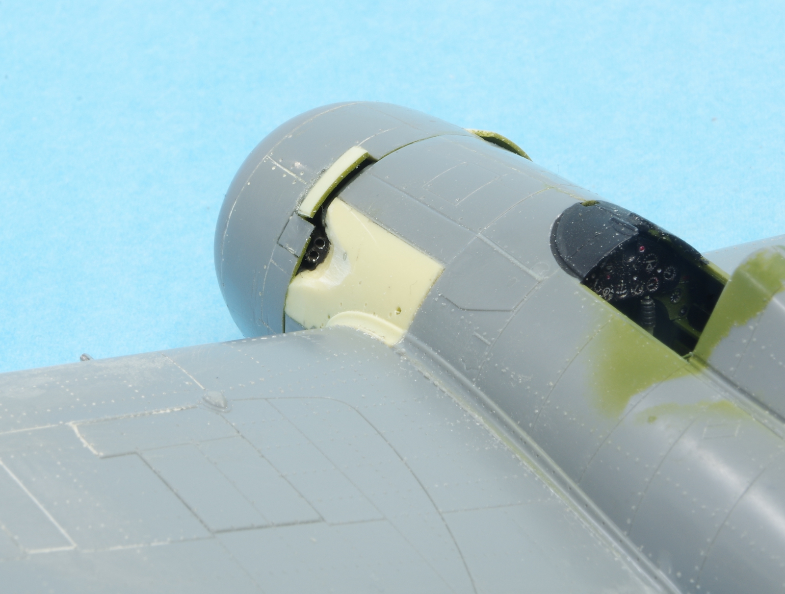
All the Tamiya cowl flap detail was filled with CA and sanded smooth. Cowl flaps were cut from the KMC resin cowl. This is the first attempt to get them in the correct location, but it took me three tries before they looked right compared to photos. They were located much too low on the KMC cowl.
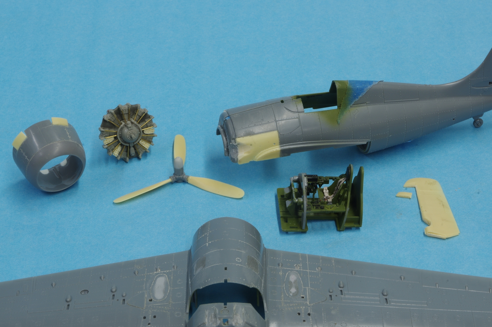
The Vector engine and other parts in progress. Eduard seat belts and pre-painted instrument panel details were added. I have heard people say that the floor on the FM-2 was solid outside the rudder foot rails but I did not find that supported by photographs. There was some disappointment
registered while building up the cockpit when I dropped the rudder pedals on the floor and then gracelessly stepped on them. Tamiya was kind enough to send a replacement part rather swiftly even though I had admitted the mode of failure.
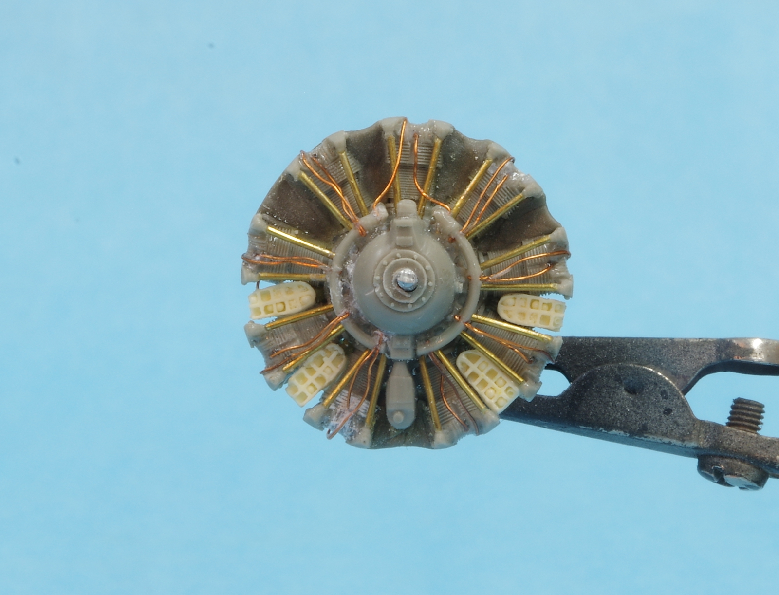
The Vector engine. Brass pushrod housings and bell wire ignition wiring was added, and Epoxyscuplt was used to make the lamb chop baffles between the cylinders. This is not the Vector engine that comes with the Vector conversion set for the HobbyBoss FM-2, which does have the lamb chops in resin. An .060 diameter length of music wire has been installed in a hole drilled in the crankcase for later propeller installation.
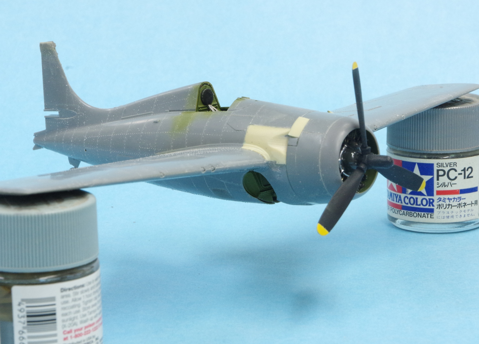
The Vector engine in the cowl. The cowl flaps are now in their final position. The inside of the fuselage, cowl, and landing bay are painted zinc chromate green. Here is the source:
http://www.ipmsstockholm.org/magazine/2004/05/stuff_eng_interior_colours_us_part3.htm
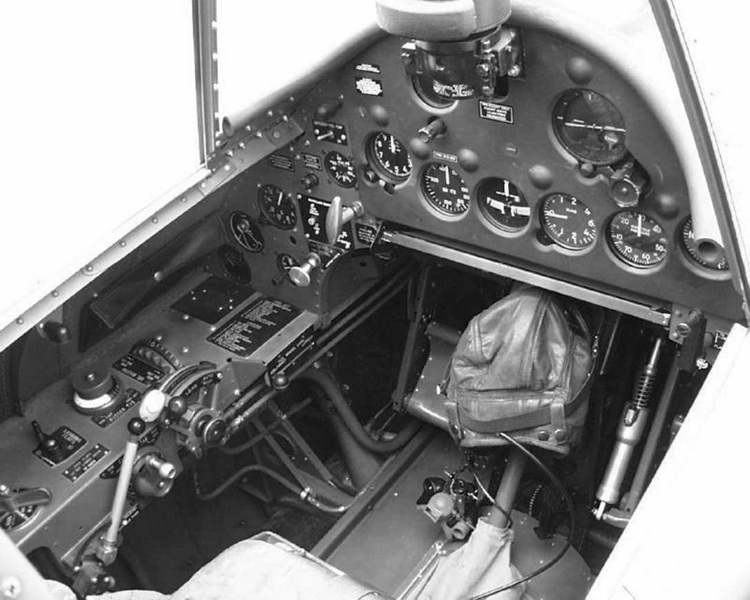
A photo of an FM-2 cockpit. It is identifiable as an FM-2 by the fuel filler tube visible to the left of the rudder pedal, the larger tube below the smaller curved pipe. This was moved forward from a position beside the seat of the F4F and FM-1. This image is from a very good page on F4F variants, here is the link to it:
http://www.scharch.org/Ed_Scharch/usn-aircraft/05-f4f-wildcat.html
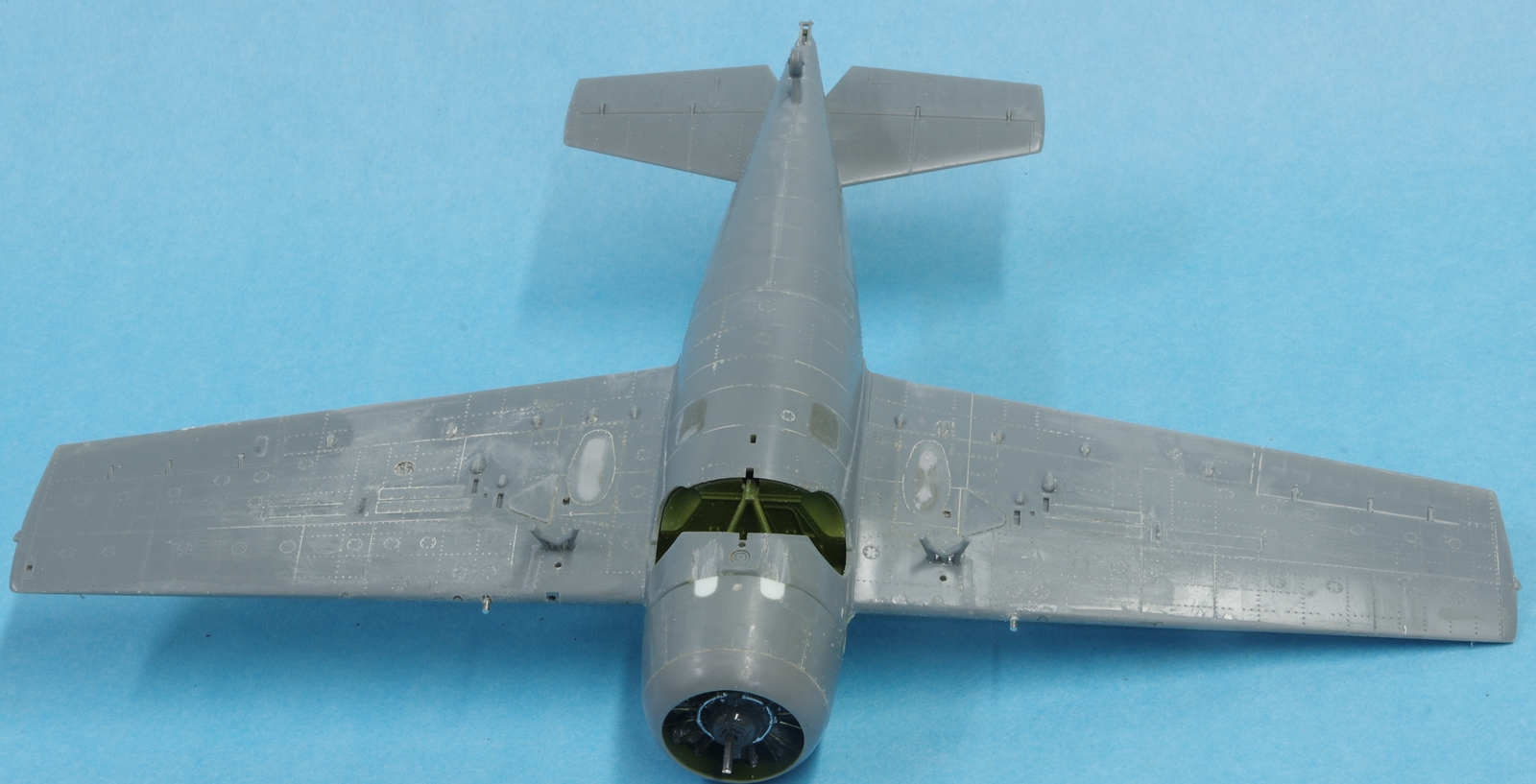
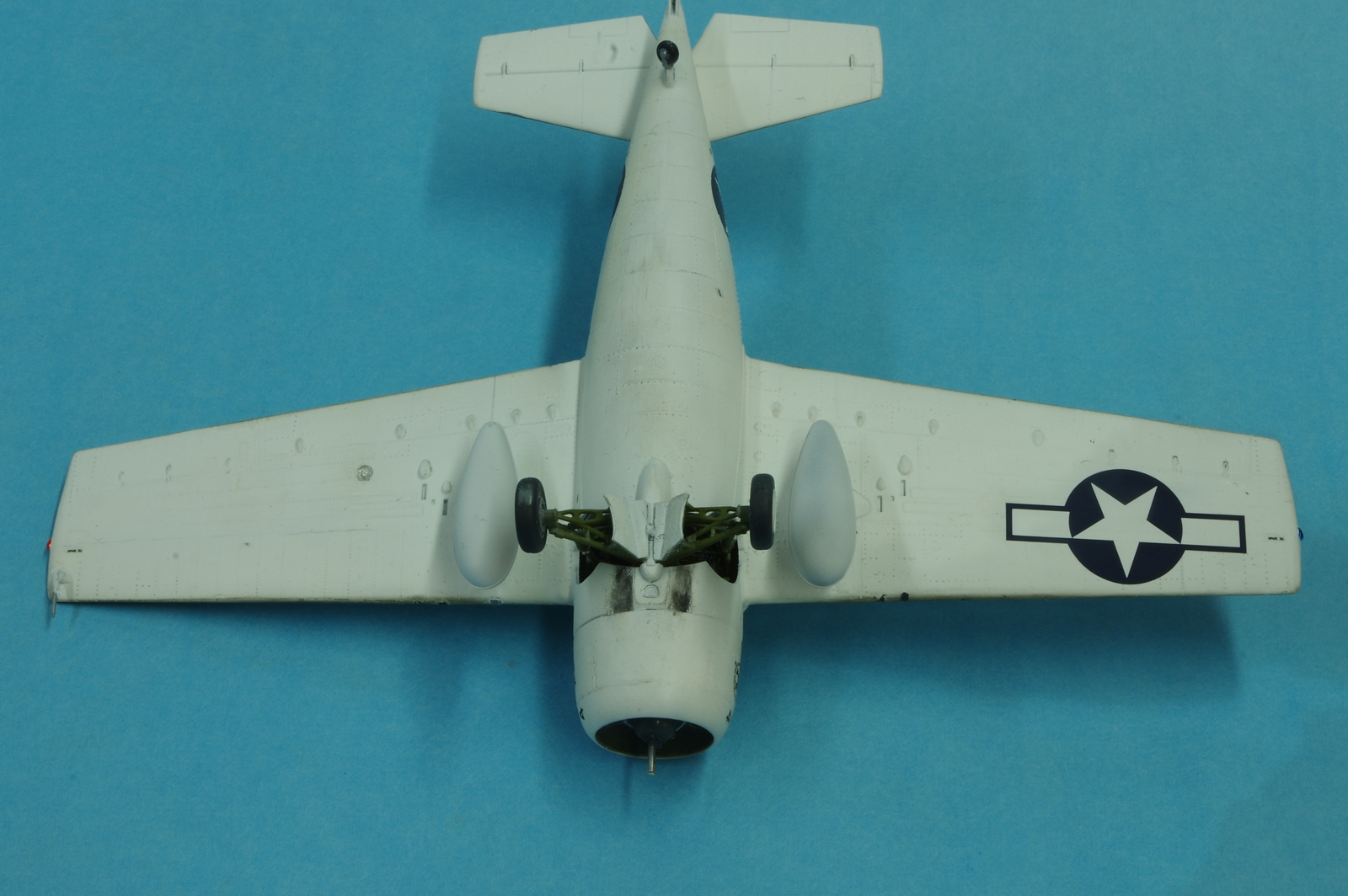
Work progresses on the underside of the wing. Never mind the inboard guns that are protruding. MIndfade to be corrected later, only the F4F-3 had that feature.
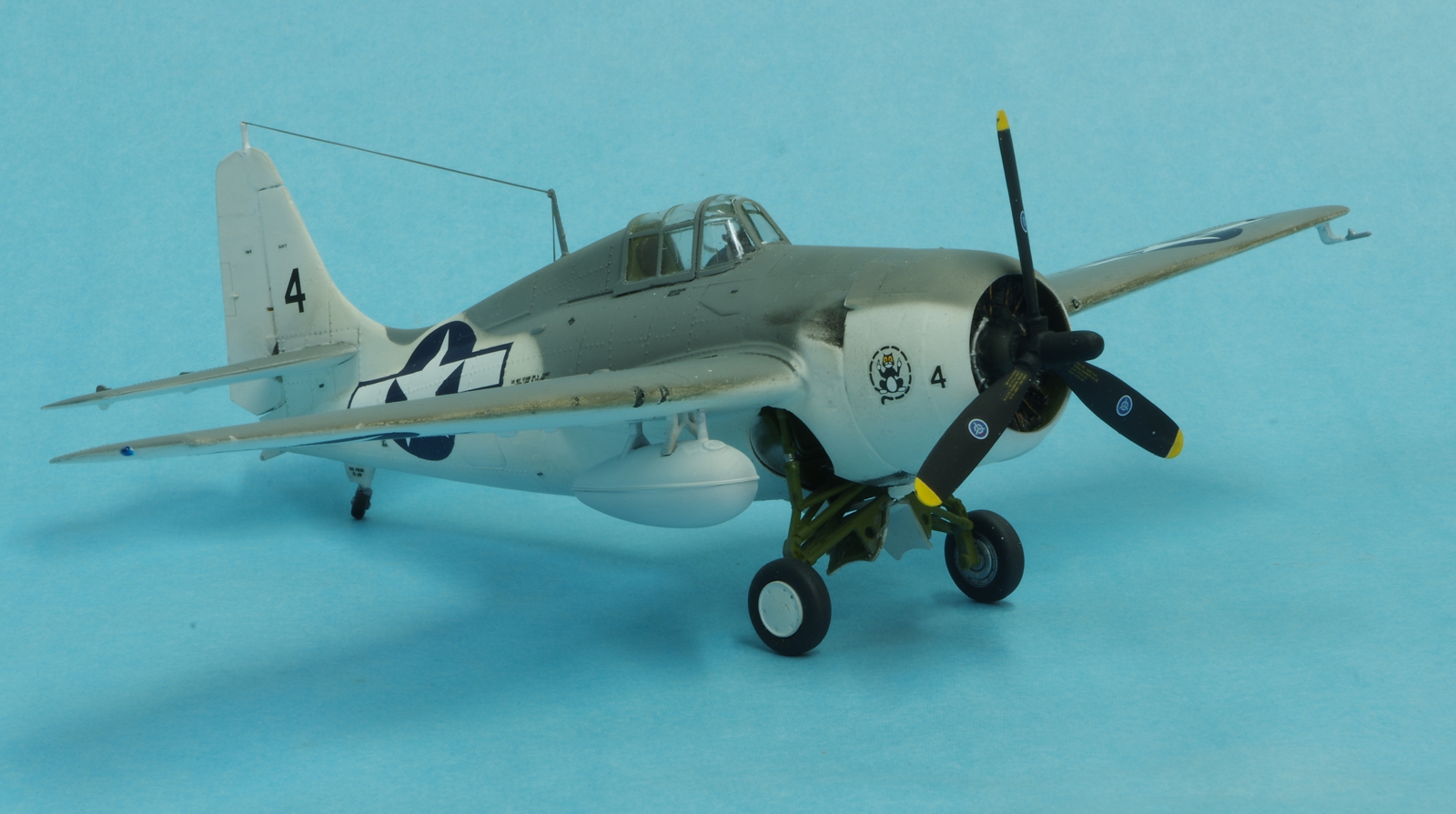
The left side exhaust, which had two stacks.
The right side exhaust, which had three stacks.
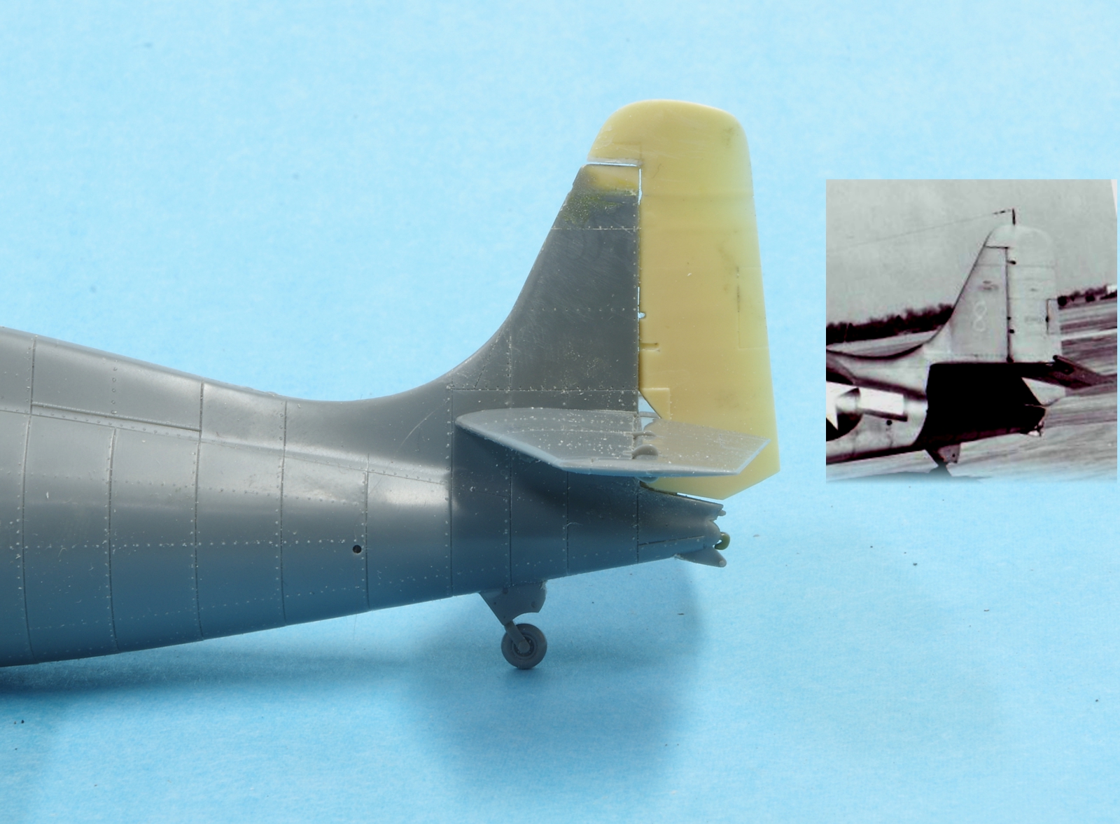
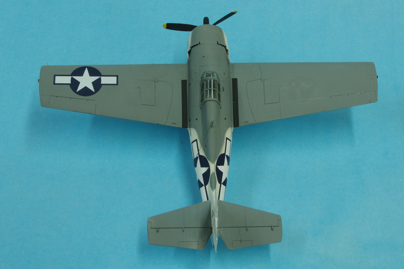
The fin and rudder.
The KMC conversion parts and instructions. The rudder needed modification as the aerodynamic counterbalance came down too far. The lower part was cut off and attached to the fin so that it looked more like photos to me. I didn't use the cowl except as a guide for positioning the cowl flaps, which caused trouble because they were too low on the cowl and did not align with the exhaust depressions. The cowl didn't fit the Tamiya kit very well. They tell you to put inlet ducts in the bottom of the cowl which is not accurate for the FM-2. They do tell you to remove the magnetos from the kit engine but you are still left with the wrong number of cylinders and incorrect nose section.
The FM-2 had metal plates where the lower fuselage window were on earlier Wildcats so they were backed with plastic card and filled with Epoxysculpt. The oil cooler was behind the engine in the accessory compartment so the remnants of the wing oil coolers were ground away and the remaining depressions filled with Epoxysculpt as well. The FM-2 had two exhaust stacks on the bottom like the earlier Wildcats but they were smaller and under the cowl with larger reliefs into the fuselage behind the cowl. More grinding and filling. Since the FM-2 had no outboard guns the accompanying shell chutes and bulges, ammunition loading doors below and gun access doors on top of the wings must be removed where the outboard guns were on the F4F-4 and FM-1.
The change to the KMC FM-2 rudder.
Epoxysculpt was used to fill in behind the KMC exhaust reliefs as they were too shallow to allow representation of the exhaust pipes under the cowl sides. It was also used to modify the propeller hub, although for many FM-2's the Tamiya hub would be correct.
The front cowl ring from the Sword FM-2 was adapted to the Tamiya cowl.
All the Tamiya cowl flap detail was filled with CA and sanded smooth. Cowl flaps were cut from the KMC resin cowl. This is the first attempt to get them in the correct location, but it took me three tries before they looked right compared to photos. They were located much too low on the KMC cowl.
The Vector engine and other parts in progress. Eduard seat belts and pre-painted instrument panel details were added. I have heard people say that the floor on the FM-2 was solid outside the rudder foot rails but I did not find that supported by photographs. There was some disappointment
registered while building up the cockpit when I dropped the rudder pedals on the floor and then gracelessly stepped on them. Tamiya was kind enough to send a replacement part rather swiftly even though I had admitted the mode of failure.
The Vector engine. Brass pushrod housings and bell wire ignition wiring was added, and Epoxyscuplt was used to make the lamb chop baffles between the cylinders. This is not the Vector engine that comes with the Vector conversion set for the HobbyBoss FM-2, which does have the lamb chops in resin. An .060 diameter length of music wire has been installed in a hole drilled in the crankcase for later propeller installation.
The Vector engine in the cowl. The cowl flaps are now in their final position. The inside of the fuselage, cowl, and landing bay are painted zinc chromate green. Here is the source:
http://www.ipmsstockholm.org/magazine/2004/05/stuff_eng_interior_colours_us_part3.htm
A photo of an FM-2 cockpit. It is identifiable as an FM-2 by the fuel filler tube visible to the left of the rudder pedal, the larger tube below the smaller curved pipe. This was moved forward from a position beside the seat of the F4F and FM-1. This image is from a very good page on F4F variants, here is the link to it:
http://www.scharch.org/Ed_Scharch/usn-aircraft/05-f4f-wildcat.html
Work progresses on the underside of the wing. Never mind the inboard guns that are protruding. MIndfade to be corrected later, only the F4F-3 had that feature.
The left side exhaust, which had two stacks.
The right side exhaust, which had three stacks.
The fin and rudder.


")
 :drinks